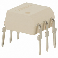
G3VM-61BR Omron, G3VM-61BR Datasheet - Page 4

G3VM-61BR
Manufacturer Part Number
G3VM-61BR
Description
MOSFET TH Relay
Manufacturer
Omron
Series
G3VMr
Datasheets
1.G3VM-2FL.pdf
(6 pages)
2.G3VM-2FL.pdf
(4 pages)
3.G3VM-61ER.pdf
(4 pages)
4.G3VM-61BR.pdf
(4 pages)
Specifications of G3VM-61BR
Circuit
SPST-NO (1 Form A)
Output Type
AC, DC
On-state Resistance
100 mOhm
Load Current
2.5A
Voltage - Input
1.33VDC
Voltage - Load
0 ~ 60 V
Mounting Type
Through Hole
Termination Style
PC Pin
Package / Case
6-DIP (0.300", 7.62mm)
Control Voltage Range
1.18 V to 1.48 V
Load Voltage Rating
60 V
Off State Leakage Current (max)
1 uA
Load Current Rating
2500 mA
Contact Form
1 Form A
Output Device
MOSFET
Mounting Style
PCB
Relay Type
MOSFET Relay
Turn-on Switching
FET
Load Voltage Max
60V
On State Resistance Max
0.1ohm
Contact Configuration
SPST-NO
Forward Current If
30mA
Relay Terminals
Through Hole
Svhc
No SVHC (20-Jun-2011)
Rohs Compliant
Yes
Lead Free Status / RoHS Status
Lead free / RoHS Compliant
Other names
G3VM61BR
Z2442
Z2442
Available stocks
Company
Part Number
Manufacturer
Quantity
Price
Company:
Part Number:
G3VM-61BR
Manufacturer:
LUMEX
Quantity:
40 000
G3VM Series
Load Connection
Do not short-circuit the input and output terminals while the relay
is operating or the relay may malfunction.
AC Connection
DC Single Connection
DC Parallel Connection
Load
Load
Load
Load
Solder Mounting
Perform solder mounting under the following recommended con-
ditions to prevent the temperature of the Relays from rising.
<Flow Soldering>
Through-hole Mounting (Once Only)
Note:
<Reflow Soldering>
Surface Mounting DIP or SOP Packages (Twice Max.)
Surface Mounting SSOP Packages (Twice Max.)
Note:
Manual Soldering (Once Only)
Manually solder at 350 ° C for 3 s or less or at 260 ° C for 10 s or
less.
SSOP Handling Precautions
<Humidity-resistant Packaging>
Component packages can crack if surface-mounted components
that have absorbed moisture are subjected to thermal stress
when mounting. To prevent this, observe the following precau-
tions.
Lead solder
SnPb
Lead-free solder
SnAgCu
Lead solder
SnPb
Lead-free solder
SnAgCu
Lead solder
SnPb
Lead-free solder
SnAgCu
1. Unopened components can be stored in the packaging at 5
2. After the packaging has been opened, components can be
3. If, after opening the packaging, the humidity indicator turns
4. If the same components are baked repeatedly, the tape
5. Do not throw or drop components. If the laminated packag-
6. Tape cut SSOPs are packaged without humidity resistance.
Solder type
Solder type
Solder type
to 30 ° C and a humidity of 90% max., but they should be
used within 12 months.
stored at 5 to 30 ° C and a humidity of 60% max., but they
should be mounted within 168 hours.
pink to the 30% mark or the expiration data is exceeded,
bake the components while they are still on the taping reel,
and use them within 72 hours. Do not bake the same com-
ponents more than once.
detachment strength will change, causing problems when
mounting. When mounting using dehumidifying measures,
always take countermeasures against component damage
from static electricity.
ing material is damaged, airtightness will be lost.
Use manual soldering to mount them.
Baking conditions: 60 ± 5 ° C, 64 to 72 h
Expiration date:
We recommend that the suitability of solder mounting be
verified under actual conditions.
1. We recommend that the suitability of solder mounting
2. Tape cut SSOPs are packaged without humidity resis-
be verified under actual conditions.
tance. Use manual soldering to mount them.
150 ° C
60 to 120 s
150 ° C
60 to 120 s
140 → 160 ° C
60 to 120 s
180 → 190 ° C
60 to 120 s
140 → 160 ° C
60 to 120 s
150 → 180 ° C
120 s max.
Preheating
Preheating
Preheating
(given on the label)
12 months from the seal date
210 ° C
30 s max.
230 ° C
30 to 50 s
210 ° C
30 s max.
230 ° C
30 s max.
230 to 260 ° C
10 s max.
245 to 260 ° C
10 s max.
G3VM Series
Soldering
Soldering
Soldering
Peak
240 ° C max.
Peak
260 ° C max.
Peak
240 ° C max.
Peak
250 ° C max.
5


