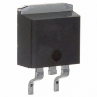
43CTQ100SPBF Vishay, 43CTQ100SPBF Datasheet

DIODE SCHOTTKY 100V 20A D2PAK

43CTQ100SPBF

Manufacturer Part Number
43CTQ100SPBF
Description
DIODE SCHOTTKY 100V 20A D2PAK
Manufacturer
Vishay
Datasheet

Specifications of 43CTQ100SPBF

Voltage - Forward (vf) (max) @ If
810mV @ 20A
Current - Reverse Leakage @ Vr
1mA @ 100V
Current - Average Rectified (io) (per Diode)
20A
Voltage - Dc Reverse (vr) (max)
100V
Diode Type
Schottky
Speed
Fast Recovery =< 500ns, > 200mA (Io)
Diode Configuration
1 Pair Common Cathode
Mounting Type
Surface Mount
Package / Case
D²Pak, TO-263 (2 leads + tab)
Product
Schottky Diodes
Peak Reverse Voltage
100 V
Forward Continuous Current
20 A
Max Surge Current
850 A
Configuration
Dual Common Cathode
Forward Voltage Drop
0.98 V @ 40 A
Maximum Reverse Leakage Current
1000 uA
Operating Temperature Range
- 55 C to 175 C
Mounting Style
SMD/SMT
Lead Free Status / RoHS Status
Lead free / RoHS Compliant
Reverse Recovery Time (trr)
-
Lead Free Status / Rohs Status
Lead free / RoHS Compliant
Other names
*43CTQ100SPBF
VS-43CTQ100SPBF
VS-43CTQ100SPBF
VS43CTQ100SPBF
VS43CTQ100SPBF

Available stocks

Company
Part Number
Manufacturer
Quantity
Price
Part Number:
43CTQ100SPBF
Manufacturer:
VIR
Quantity:
850
Part Number:
43CTQ100SPBF
Manufacturer:
VISHAY/威世
Quantity:
20 000
Company:
Part Number:
43CTQ100SPBF
Quantity:
70 000
Company:
Part Number:
43CTQ100SPBF
Quantity:
70 000
* Pb containing terminations are not RoHS compliant, exemptions may apply
Document Number: 94224
Revision: 29-Jul-08
PRODUCT SUMMARY
MAJOR RATINGS AND CHARACTERISTICS
SYMBOL
I
V
I
V
T
VOLTAGE RATINGS
PARAMETER
Maximum DC reverse voltage
Maximum working peak reverse voltage
ABSOLUTE MAXIMUM RATINGS
PARAMETER
Maximum average
forward current
See fig. 5
Maximum peak one cycle non-repetitive
surge current per leg
See fig. 7
Non-repetitive avalanche energy per leg
Repetitive avalanche current per leg
F(AV)
FSM
RRM
F
J
Anode
43CTQ...SPbF
1
I
F(AV)
Common
D
cathode
V
common
cathode
2
R
Base
PAK
2
2
Anode
3
per device
Rectangular waveform
t
20 Apk, T
Range
Anode
p
= 5 µs sine
per leg
43CTQ...-1PbF
1
For technical questions, contact: diodes-tech@vishay.com
Schottky Rectifier, 2 x 20 A
Common
TO-262
cathode
common
cathode
80/100 V
2 x 20 A
J
Base
= 125 °C (per leg)
SYMBOL
SYMBOL
2
2
V
I
CHARACTERISTICS
I
F(AV)
E
FSM
I
V
RWM
AR
AS
R
Anode
3
50 % duty cycle at T
5 µs sine or 3 µs rect. pulse
10 ms sine or 6 ms rect. pulse
T
Current decaying linearly to zero in 1 µs
Frequency limited by T
J
= 25 °C, I
43CTQ080-1PbF
43CTQ080SPbF
80
AS
FEATURES
• 175 °C T
• Center tap configuration
• Low forward voltage drop
• High
• High frequency operation
• Guard ring for enhanced ruggedness and long term
• Lead (Pb)-free (“PbF” suffix)
• Designed and qualified for Q101 level
DESCRIPTION
This center tap Schottky rectifier series has been optimized
for low reverse leakage at high temperature. The proprietary
barrier technology allows for reliable operation up to 175 °C
junction temperature. Typical applications are in switching
power supplies, freewheeling diodes, and reverse battery
protection.
= 0.50 A, L = 60 mH
encapsulation for enhanced mechanical strength and
moisture resistance
reliability
TEST CONDITIONS
43CTQ...SPbF/43CTQ...-1PbF
C
= 135 °C, rectangular waveform
J
maximum V
purity,
J
operation
Vishay High Power Products
Following any rated load
condition and with rated
V
RRM
43CTQ100-1PbF
43CTQ100SPbF
A
high
= 1.5 x V
- 55 to 175
applied
VALUES
80/100
0.67
850
40
100
temperature
R
typical
VALUES
epoxy
7.50
0.50
850
275
20
40
www.vishay.com
UNITS
UNITS
°C
A
V
A
V
V
RoHS*
COMPLIANT
UNITS
Available
mJ
A
A
1

Related parts for 43CTQ100SPBF

43CTQ100SPBF Summary of contents

Page 1

... AR Frequency limited For technical questions, contact: diodes-tech@vishay.com Vishay High Power Products operation J purity, high temperature epoxy VALUES 40 80/100 850 0. 175 43CTQ100SPbF 43CTQ100-1PbF 100 VALUES 20 40 Following any rated load 850 condition and with rated 275 V applied RRM 7.50 0.50 maximum typical ...

Page 2

... Measured lead to lead 5 mm from package body S dV/dt Rated V R SYMBOL TEST CONDITIONS Stg R DC operation thJC R Mounting surface, smooth and greased thCS 2 Case style D PAK Case style TO-262 For technical questions, contact: diodes-tech@vishay.com VALUES 0. °C J 0.98 0. 125 ° Rated 0.71 0.43 1480 8 ...

Page 3

... Fig Typical Junction Capacitance vs. Reverse Voltage (Per Leg 0. 0. 0.33 Single pulse 0.20 0.001 0.01 0 Rectangular Pulse Duration (s) 1 Fig Maximum Thermal Impedance Z thJC For technical questions, contact: diodes-tech@vishay.com Vishay High Power Products T = 175 ° 150 ° 125 ° 100 ° ° ...

Page 4

... Fig Maximum Non-Repetitive Surge Current (Per Leg) L IRFP460 D.U.T. Freewheel = 25 Ω 40HFL40S02 Fig Unclamped Inductive Test Circuit ; thJC at (I /D) (see fig. 6); F(AV D For technical questions, contact: diodes-tech@vishay.com Average Forward Current (A) F(AV) Fig Forward Power Loss Characteristics (Per Leg) 10 000 High-speed switch ...

Page 5

... None = Tube (50 pieces) TRL = Tape and reel (left oriented - for D TRR = Tape and reel (right oriented - for D - None = Standard production PbF = Lead (Pb)-free LINKS TO RELATED DOCUMENTS For technical questions, contact: diodes-tech@vishay.com Vishay High Power Products TRL PbF 7 8 080 = 80 V 100 = 100 V ...

Page 6

... Vishay disclaims any and all liability arising out of the use or application of any product described herein or of any information provided herein to the maximum extent permitted by law. The product specifications do not expand or otherwise modify Vishay’ ...

Related keywords