40L15CT Vishay, 40L15CT Datasheet - Page 3
40L15CT
Manufacturer Part Number
40L15CT
Description
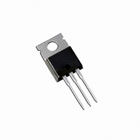
DIODE SCHOTTKY 15V 20A TO-220AB
Manufacturer
Vishay
Datasheet
1.40L15CTPBF.pdf
(6 pages)
Specifications of 40L15CT
Voltage - Forward (vf) (max) @ If
410mV @ 19A
Current - Reverse Leakage @ Vr
10mA @ 15V
Current - Average Rectified (io) (per Diode)
20A
Voltage - Dc Reverse (vr) (max)
15V
Diode Type
Schottky
Speed
Fast Recovery =< 500ns, > 200mA (Io)
Diode Configuration
1 Pair Common Cathode
Mounting Type
Through Hole
Package / Case
TO-220-3 (Straight Leads)
Product
Schottky Rectifiers
Peak Reverse Voltage
15 V
Forward Continuous Current
20 A
Max Surge Current
700 A
Configuration
Dual Common Cathode
Forward Voltage Drop
0.52 V at 40 A
Maximum Reverse Leakage Current
10 mA
Operating Temperature Range
- 55 C to + 125 C
Mounting Style
Through Hole
Lead Free Status / RoHS Status
Contains lead / RoHS non-compliant
Reverse Recovery Time (trr)
-
Lead Free Status / RoHS Status
Contains lead / RoHS non-compliant, Lead free / RoHS Compliant
Other names
*40L15CT
VS-40L15CT
VS-40L15CT
VS40L15CT
VS40L15CT
VS-40L15CT
VS-40L15CT
VS40L15CT
VS40L15CT
Available stocks
Company
Part Number
Manufacturer
Quantity
Price

Company:
Part Number:
40L15CT
Manufacturer:
IR
Quantity:
18 900
Company:
Part Number:
40L15CT-1
Manufacturer:
IR
Quantity:
18 900
Company:
Part Number:
40L15CT-1PBF
Manufacturer:
VIR
Quantity:
600
Company:
Part Number:
40L15CTPBF
Manufacturer:
VIR
Quantity:
200
Part Number:
40L15CTPBF
Manufacturer:
IR
Quantity:
20 000


Document Number: 93342
Revision: 22-Aug-08
Fig. 1 - Maximum Forward Voltage Drop Characteristics
1000
100
10
1
0
0.01
0.2
0.1
10
0.00001
V
1
FM
0.4
- Forward Voltage Drop (V)
0.6
(thermal resistance)
(Per Leg)
0.0001
Single pulse
0.8
Fig. 4 - Maximum Thermal Impedance Z
Fig. 3 - Typical Junction Capacitance vs. Reverse Voltage (Per Leg)
For technical questions, contact: diodes-tech@vishay.com
1.0
T
T
T
J
J
J
= 125 °C
= 75 °C
= 25 °C
10 000
1.2
1000
Schottky Rectifier, 2 x 20 A
100
0.001
1.4
0
t
1
1.6
- Rectangular Pulse Duration (s)
V
5
R
- Reverse Voltage (V)
0.01
D = 0.75
D = 0.50
D = 0.33
D = 0.25
D = 0.20
T
J
10
= 25 °C
thJC
0.1
Characteristics (Per Leg)
1000
15
100
0.1
10
1
Fig. 2 - Typical Values of Reverse Current vs.
0
Vishay High Power Products
20
1
T
Notes:
1. Duty factor D = t
2. Peak T
3
Reverse Voltage (Per Leg)
J
V
= 100 °C
R
- Reverse Voltage (V)
J
P
6
= P
T
DM
J
10
= 75 °C
DM
t
1
T
x Z
J
t
2
1
= 50 °C
/t
9
thJC
2
T
+ T
J
= 25 °C
40L15CT
C
100
12
www.vishay.com
15
3
Related parts for 40L15CT
Image
Part Number
Description
Manufacturer
Datasheet
Request
R

Part Number:
Description:
357-036-542-201 CARDEDGE 36POS DL .156 BLK LOPRO
Manufacturer:
Vishay
Datasheet:
Part Number:
Description:
357-036-542-201 CARDEDGE 36POS DL .156 BLK LOPRO
Manufacturer:
Vishay
Datasheet:
Part Number:
Description:
357-036-542-201 CARDEDGE 36POS DL .156 BLK LOPRO
Manufacturer:
Vishay
Datasheet:
Part Number:
Description:
357-036-542-201 CARDEDGE 36POS DL .156 BLK LOPRO
Manufacturer:
Vishay
Datasheet:
Part Number:
Description:
357-036-542-201 CARDEDGE 36POS DL .156 BLK LOPRO
Manufacturer:
Vishay
Datasheet:
Part Number:
Description:
357-036-542-201 CARDEDGE 36POS DL .156 BLK LOPRO
Manufacturer:
Vishay
Datasheet:
Part Number:
Description:
357-036-542-201 CARDEDGE 36POS DL .156 BLK LOPRO
Manufacturer:
Vishay
Datasheet:
Part Number:
Description:
357-036-542-201 CARDEDGE 36POS DL .156 BLK LOPRO
Manufacturer:
Vishay
Datasheet:
Part Number:
Description:
357-036-542-201 CARDEDGE 36POS DL .156 BLK LOPRO
Manufacturer:
Vishay
Datasheet:
Part Number:
Description:
357-036-542-201 CARDEDGE 36POS DL .156 BLK LOPRO
Manufacturer:
Vishay
Datasheet:
Part Number:
Description:
357-036-542-201 CARDEDGE 36POS DL .156 BLK LOPRO
Manufacturer:
Vishay
Datasheet:
Part Number:
Description:
357-036-542-201 CARDEDGE 36POS DL .156 BLK LOPRO
Manufacturer:
Vishay
Datasheet:
Part Number:
Description:
357-036-542-201 CARDEDGE 36POS DL .156 BLK LOPRO
Manufacturer:
Vishay
Datasheet:
Part Number:
Description:
357-036-542-201 CARDEDGE 36POS DL .156 BLK LOPRO
Manufacturer:
Vishay
Datasheet:
Part Number:
Description:
357-036-542-201 CARDEDGE 36POS DL .156 BLK LOPRO
Manufacturer:
Vishay
Datasheet: