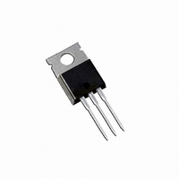
HFA16TA60CPBF Vishay, HFA16TA60CPBF Datasheet - Page 2

HFA16TA60CPBF
Manufacturer Part Number
HFA16TA60CPBF
Description
DIODE HEXFRED 600V 8A TO220AB
Manufacturer
Vishay
Series
HEXFRED®r
Datasheets
1.HFA16TA60CPBF.pdf
(7 pages)
2.HFA16TA60CPBF.pdf
(6 pages)
3.HFA16TA60CPBF.pdf
(8 pages)
Specifications of HFA16TA60CPBF
Diode Configuration
1 Pair Common Cathode
Diode Type
Standard
Voltage - Forward (vf) (max) @ If
1.7V @ 8A
Current - Reverse Leakage @ Vr
5µA @ 600V
Current - Average Rectified (io) (per Diode)
8A (DC)
Voltage - Dc Reverse (vr) (max)
600V
Reverse Recovery Time (trr)
55ns
Speed
Fast Recovery =< 500ns, > 200mA (Io)
Mounting Type
Through Hole
Package / Case
TO-220-3 (Straight Leads)
Product
Ultra Fast Recovery Rectifier
Configuration
Dual Common Cathode
Reverse Voltage
600 V
Forward Voltage Drop
2.1 V
Recovery Time
55 ns
Forward Continuous Current
16 A
Max Surge Current
60 A
Reverse Current Ir
5 uA
Mounting Style
Through Hole
Maximum Operating Temperature
+ 150 C
Minimum Operating Temperature
- 55 C
Repetitive Reverse Voltage Vrrm Max
600V
Forward Current If(av)
8A
Forward Voltage Vf Max
2.1V
Lead Free Status / RoHS Status
Lead free / RoHS Compliant
Lead Free Status / RoHS Status
Lead free / RoHS Compliant, Lead free / RoHS Compliant
Other names
*HFA16TA60CPBF
VS-HFA16TA60CPBF
VS-HFA16TA60CPBF
VSHFA16TA60CPBF
VSHFA16TA60CPBF
VS-HFA16TA60CPBF
VS-HFA16TA60CPBF
VSHFA16TA60CPBF
VSHFA16TA60CPBF
VS-HFA16TA60CPbF
Vishay Semiconductors
www.vishay.com
2
THE PRODUCTS DESCRIBED HEREIN AND THIS DOCUMENT ARE SUBJECT TO SPECIFIC DISCLAIMERS, SET FORTH AT
ELECTRICAL SPECIFICATIONS PER LEG (T
PARAMETER
Cathode to anode
breakdown voltage
Maximum forward voltage
Maximum reverse
leakage current
Junction capacitance
Series inductance
DYNAMIC RECOVERY CHARACTERISTICS PER LEG (T
PARAMETER
Reverse recovery time
See fig. 5 and 10
Peak recovery current
See fig. 6
Reverse recovery charge
See fig. 7
Peak rate of fall recovery
current during t
See fig. 8
THERMAL - MECHANICAL SPECIFICATIONS PER LEG
PARAMETER
Lead temperature
Junction to case,
single leg conducting
Junction to case,
both legs conducting
Thermal resistance,
junction to ambient
Thermal resistance,
case to heatsink
Weight
Mounting torque
Marking device
b
DiodesAmericas@vishay.com, DiodesAsia@vishay.com,
For technical questions within your region, please contact one of the following:
dI
dI
SYMBOL
SYMBOL
SYMBOL
(rec)M
(rec)M
R
I
I
R
R
T
V
V
RRM1
RRM2
Q
Q
I
C
L
t
t
RM
thCS
t
lead
thJC
thJA
BR
FM
rr1
rr2
rr
rr1
rr2
S
T
/dt1
/dt2
Ultrafast Soft Recovery Diode, 2 x 8 A
This document is subject to change without notice.
I
I
I
I
V
T
V
Measured lead to lead 5 mm from package
body
0.063" from case (1.6 mm) for 10 s
Typical socket mount
Mounting surface, flat, smooth and greased
Case style TO-220AB
I
T
T
T
T
T
T
T
T
R
F
F
F
F
R
J
R
J
J
J
J
J
J
J
J
= 8 A
= 16 A
= 8 A, T
= 100 μA
= 1.0 A, dI
= 125 °C, V
= 25 °C
= 125 °C
= 25 °C
= 125 °C
= 25 °C
= 125 °C
= 25 °C
= 125 °C
= V
= 200 V
R
rated
J
= 125 °C
TEST CONDITIONS
TEST CONDITIONS
TEST CONDITIONS
F
J
/dt = 200 A/μs, V
R
HEXFRED
= 25 °C unless otherwise specified)
= 0.8 x V
I
dI
V
R
F
R
F
rated
= 8.0 A
/dt = 200 A/μs
= 200 V
J
®
R
= 25 °C unless otherwise specified)
= 30 V
DiodesEurope@vishay.com
See fig. 1
See fig. 2
See fig. 3
MIN.
MIN.
MIN.
(5.0)
600
6.0
-
-
-
-
-
-
-
-
-
-
-
-
-
-
-
-
-
-
-
-
-
-
-
TYP.
TYP.
TYP.
0.07
124
240
210
100
3.5
4.5
0.5
2.0
1.4
1.7
1.4
0.3
8.0
HFA16TA60C
10
18
37
55
65
www.vishay.com/doc?91000
-
-
-
-
-
-
Document Number: 94058
Revision: 09-May-11
MAX.
MAX.
MAX.
1.75
500
138
360
300
(10)
3.5
1.7
2.1
1.7
5.0
5.0
8.0
55
90
80
12
25
-
-
-
-
-
-
-
-
kgf · cm
(lbf · in)
UNITS
UNITS
UNITS
A/μs
K/W
μA
nH
nC
oz.
pF
°C
ns
V
A
g


