MMBD6100LT1G ON Semiconductor, MMBD6100LT1G Datasheet - Page 3
MMBD6100LT1G
Manufacturer Part Number
MMBD6100LT1G
Description
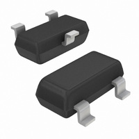
DIODE SWITCH DUAL 70V SOT23S
Manufacturer
ON Semiconductor
Specifications of MMBD6100LT1G
Voltage - Forward (vf) (max) @ If
1.1V @ 100mA
Current - Reverse Leakage @ Vr
100nA @ 50V
Current - Average Rectified (io) (per Diode)
200mA (DC)
Voltage - Dc Reverse (vr) (max)
70V
Reverse Recovery Time (trr)
4ns
Diode Type
Standard
Speed
Small Signal =< 200mA (Io), Any Speed
Diode Configuration
1 Pair Common Cathode
Mounting Type
Surface Mount
Package / Case
SOT-23-3, TO-236-3, Micro3™, SSD3, SST3
Product
Switching Diodes
Peak Reverse Voltage
70 V
Forward Continuous Current
0.2 A
Max Surge Current
0.5 A
Configuration
Dual Common Cathode
Recovery Time
4 ns
Forward Voltage Drop
1.1 V
Maximum Reverse Leakage Current
0.1 uA
Operating Temperature Range
- 55 C to + 150 C
Maximum Operating Temperature
+ 150 C
Minimum Operating Temperature
- 55 C
Mounting Style
SMD/SMT
Capacitance, Junction
2.5 pF
Current, Forward
200 mA
Current, Surge
500 mA
Package Type
SOT-23 (TO-236)
Power Dissipation
225 mW
Primary Type
Rectifier
Speed, Switching
Switching
Temperature, Junction, Maximum
+150 °C
Temperature, Operating
-55 to +150 °C
Time, Recovery
4 ns
Voltage, Forward
1.1 V
Voltage, Reverse
70 V
Lead Free Status / RoHS Status
Lead free / RoHS Compliant
Other names
MMBD6100LT1GOS
MMBD6100LT1GOS
MMBD6100LT1GOSTR
MMBD6100LT1GOS
MMBD6100LT1GOSTR
Available stocks
Company
Part Number
Manufacturer
Quantity
Price

Company:
Part Number:
MMBD6100LT1G
Manufacturer:
ON
Quantity:
30 000
Company:
Part Number:
MMBD6100LT1G
Manufacturer:
MAX
Quantity:
4 464
Part Number:
MMBD6100LT1G
Manufacturer:
ONSEMI
Quantity:
20 000


A
A1
E
1
3
D
e
2
b
H
E
*For additional information on our Pb−Free strategy and soldering
details, please download the ON Semiconductor Soldering and
Mounting Techniques Reference Manual, SOLDERRM/D.
SEE VIEW C
0.037
0.95
0.035
0.9
0.031
SOLDERING FOOTPRINT*
PACKAGE DIMENSIONS
0.8
VIEW C
L1
L
MMBD6100LT1
SOT−23 (TO−236)
CASE 318−08
ISSUE AN
q
0.25
c
3
SCALE 10:1
0.037
0.95
NOTES:
1. DIMENSIONING AND TOLERANCING PER
2. CONTROLLING DIMENSION: INCH.
3. MAXIMUM LEAD THICKNESS INCLUDES
4. 318−01 THRU −07 AND −09 OBSOLETE,
STYLE 9:
ANSI Y14.5M, 1982.
LEAD FINISH THICKNESS. MINIMUM LEAD
THICKNESS IS THE MINIMUM THICKNESS OF
BASE MATERIAL.
NEW STANDARD 318−08.
0.079
DIM
PIN 1. ANODE
A1
H
L1
A
D
E
2.0
b
c
e
L
E
inches
2. ANODE
3. CATHODE
mm
0.89
0.01
0.37
0.09
2.80
1.20
1.78
0.10
0.35
2.10
MIN
MILLIMETERS
NOM
1.00
0.06
0.44
0.13
2.90
1.30
1.90
0.20
0.54
2.40
MAX
1.11
0.10
0.50
0.18
3.04
1.40
2.04
0.30
0.69
2.64
0.035
0.001
0.015
0.003
0.047
0.070
0.004
0.014
0.083
0.110
MIN
INCHES
0.040
0.002
0.018
0.005
0.114
0.051
0.075
0.008
0.021
0.094
NOM
0.044
0.004
0.020
0.007
0.120
0.055
0.081
0.012
0.029
0.104
MAX
Related parts for MMBD6100LT1G
Image
Part Number
Description
Manufacturer
Datasheet
Request
R

Part Number:
Description:
ON Semiconductor [VOLTAGE REGULATOR]
Manufacturer:
ON Semiconductor
Datasheet:
Part Number:
Description:
357-036-542-201 CARDEDGE 36POS DL .156 BLK LOPRO
Manufacturer:
ON Semiconductor
Datasheet:
Part Number:
Description:
357-036-542-201 CARDEDGE 36POS DL .156 BLK LOPRO
Manufacturer:
ON Semiconductor
Datasheet:
Part Number:
Description:
357-036-542-201 CARDEDGE 36POS DL .156 BLK LOPRO
Manufacturer:
ON Semiconductor
Datasheet:
Part Number:
Description:
357-036-542-201 CARDEDGE 36POS DL .156 BLK LOPRO
Manufacturer:
ON Semiconductor
Datasheet:
Part Number:
Description:
357-036-542-201 CARDEDGE 36POS DL .156 BLK LOPRO
Manufacturer:
ON Semiconductor
Datasheet:
Part Number:
Description:
357-036-542-201 CARDEDGE 36POS DL .156 BLK LOPRO
Manufacturer:
ON Semiconductor
Datasheet:
Part Number:
Description:
357-036-542-201 CARDEDGE 36POS DL .156 BLK LOPRO
Manufacturer:
ON Semiconductor
Datasheet:
Part Number:
Description:
357-036-542-201 CARDEDGE 36POS DL .156 BLK LOPRO
Manufacturer:
ON Semiconductor
Datasheet:
Part Number:
Description:
357-036-542-201 CARDEDGE 36POS DL .156 BLK LOPRO
Manufacturer:
ON Semiconductor
Datasheet:
Part Number:
Description:
357-036-542-201 CARDEDGE 36POS DL .156 BLK LOPRO
Manufacturer:
ON Semiconductor
Datasheet:
Part Number:
Description:
Manufacturer:
ON Semiconductor
Datasheet:
Part Number:
Description:
Manufacturer:
ON Semiconductor
Datasheet:
Part Number:
Description:
Manufacturer:
ON Semiconductor
Datasheet: