MBR6045WT ON Semiconductor, MBR6045WT Datasheet
MBR6045WT
Specifications of MBR6045WT
Available stocks


Related parts for MBR6045WT

MBR6045WT Summary of contents
Page 1
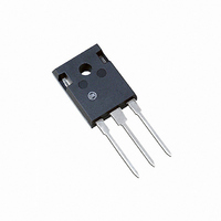
... SCHOTTKY BARRIER RECTIFIER 60 AMPERES, 45 VOLTS TO−247 2 3 CASE 340L STYLE 2 MARKING DIAGRAM MBR6045WT AYWWG A = Assembly Location Y = Year WW = Work Week G = Pb−Free Package ORDERING INFORMATION Device Package Shipping MBR6045WT TO−247 30 Units/Rail MBR6045WTG TO−247 30 Units/Rail (Pb−Free) Publication Order Number: MBR6045WT/D ...
Page 2
THERMAL CHARACTERISTICS (Per Diode) Thermal Resistance, Junction−to−Case ELECTRICAL CHARACTERISTICS Instantaneous Forward Voltage (Note Amps 25° Amps 125° Amps, T ...
Page 3
... Q 3.55 3.65 0.140 0.144 U 6.15 BSC 0.242 BSC W 2.87 3.12 0.113 0.123 STYLE 2: PIN 1. ANODE 2. CATHODE (S) 3. ANODE 2 4. CATHODES (S) ON Semiconductor Website: www.onsemi.com Order Literature: http://www.onsemi.com/orderlit For additional information, please contact your local Sales Representative MBR6045WT/D ...