A7B-C Omron, A7B-C Datasheet - Page 3
A7B-C
Manufacturer Part Number
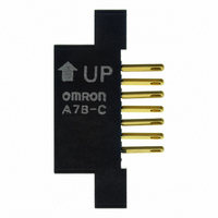
A7B-C
Description
CONNECTOR
Manufacturer
Omron
Type
Connectorr
Series
A7BS, A7BLr
Specifications of A7B-C
Accessory Type
Connector
Illumination
Not Illuminated
Height
20.5 mm
Length
37 mm
Mounting Style
Snap On
Termination Style
Solder
Width
7.8 mm
Body Orientation
Straight
Gender
PL
Pitch (mm)
2.54mm
Number Of Contact Rows
2
Lead Free Status / RoHS Status
Lead free / RoHS Compliant
For Use With/related Products
SW266 ~ SW269
For Use With
SW266 - SWITCH THUMBWHEEL BLACK BCDSW267 - SWITCH THUMBWHEEL BLACK BCDSW268 - SWITCH THUMBWHEEL EXT BRD BCDSW269 - SWITCH THUMBWHEEL EXT BRD +,-DIS
Lead Free Status / Rohs Status
Lead free / RoHS Compliant
Other names
A7BC
SW270
SW270


Dimensions
Switches
A7BS-2@@(-1)
Solder Terminals
Thumbwheel Switches with External Stoppers:
A7BS-20@-S(-1)
Refer to page 7 for details.
A7BL-206(-1)
A7BL-207(-1)
Solder Terminals,
Locking Models
• Use A7BS-S Stopper Pins to make dial display restrictions for these Switches.
• Insert the Stopper Pins in the positions required to give the desired display range. For
example, for a display range of 0 to 5, insert a Stopper Pin at position 1 (see following
diagram) to stop the display from going above 5 when the (+) button is pressed, and insert
a Stopper Pin at position 2 to stop the display from going below 0 when the (-) button is
pressed.
22
20.6
24
* If the output code is 06, the dimension is 32.5;
if the output code is 07, the dimension is 43.5.
24
3
3
Ten, 1.2 dia.
8
6.9
± 0.1
7
8
6.9
*
8
6
± 0.1
24.5
0.8
9
5
A
B
3.6
0.8
P=8
B
A
3.8
0
4
P=8
± 0.2
1
3
2
± 0.2
2.8
5.5
* If the output code is 06, the dimension is 32.5;
16
if the output code is 07, the dimension is 43.5.
* If the output code is 06 or 54, the dimension is 32.5;
if the output code is 07 or 55, the dimension is 43.5.
When setting
15.4
2.6
16
24
2
6.1
2.8
2.6
5.5
2.8
Panel Cutout
C +
Pin insertion position (1)
7
0.3
0
8
6
Panel Cutout
Panel thickness: 1 to 3
24.5
9
5
C
Panel thickness: 1 to 3
24.5
+ 0.3
*
0
0
4
Pin insertion position (2)
*
1
3
Solder terminal
2
22.4
Solder terminal
+0.4
0
22.4
20.6
20.6
+ 0.4
0
22
22
Note: 1. The dimensions above include both End
Stopper Pins
Note: 1. Two pins constitute one set.
Note: 1. The dimensions above include both End
Number of
Number of
Switches
Switches
10
(n)
10
(n)
1
2
3
4
5
6
7
8
9
1
2
3
4
5
6
7
8
9
2. Unless otherwise specified, a tolerance of
2. The first shipment is free and is attached
2. Unless otherwise specified, a tolerance of
Caps, and will increase 8 mm for each
Spacer inserted.
±0.4 mm applies to all dimensions.
The tolerance for multiple connection is
±(number of units x 0.4) mm.
to the Switch.
Order the A7BS-S separately if it is
required for maintenance.
Caps, and will increase 8 mm for each
Spacer inserted.
±0.4 mm applies to all dimensions.
The tolerance for multiple connection is
±(number of units x 0.4) mm.
2.4 dia.
(n x 8 + 8)
(n x 8 + 8)
Size A
Size A
16
24
32
40
48
56
64
72
80
88
16
24
32
40
48
56
64
72
80
88
0.4
A7BS/A7BL
(n x 8 + 6)
2.7
(n x 8 + 6)
Size B
Size B
14
22
30
38
46
54
62
70
78
86
14
22
30
38
46
54
62
70
78
86
1.2 dia.
(Unit: mm)
Size C
Size C
14.4
22.4
30.4
38.4
46.8
54.8
62.8
70.8
78.8
86.8
14.4
22.4
30.4
38.4
46.8
54.8
62.8
70.8
78.8
86.8
3
Related parts for A7B-C
Image
Part Number
Description
Manufacturer
Datasheet
Request
R

Part Number:
Description:
Endcap, Ship 1 LFT And 1 RGT
Manufacturer:
Omron
Datasheet:


Part Number:
Description:
Endcap, Ship 1 LFT And 1 RGT
Manufacturer:
Omron
Datasheet:
Part Number:
Description:
SPACER W/DECIMAL POINT
Manufacturer:
Omron
Datasheet:

Part Number:
Description:
G6S-2GLow Signal Relay
Manufacturer:
Omron Corporation
Datasheet:
Part Number:
Description:
Compact, Low-cost, SSR Switching 5 to 20 A
Manufacturer:
Omron Corporation
Datasheet:
Part Number:
Description:
Manufacturer:
Omron Corporation
Datasheet:
Part Number:
Description:
Manufacturer:
Omron Corporation
Datasheet: