B3F-3100 Omron, B3F-3100 Datasheet - Page 15
B3F-3100
Manufacturer Part Number
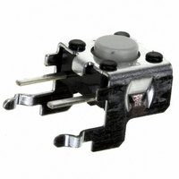
B3F-3100
Description
Pushbutton Switch,VERTICAL R/A,SPST,OFF-(ON),PC TAIL W/RETNN Terminal,PCB Hole Count:4
Manufacturer
Omron
Series
B3Fr
Specifications of B3F-3100
Circuit
SPST-NO
Switch Function
Off-Mom
Contact Rating @ Voltage
0.05A @ 24VDC
Actuator Type
Standard
Mounting Type
Through Hole
Orientation
Right Angle
Outline
7.40mm x 7.30mm
Illumination
Non-Illuminated
Operating Force
100gf
Actuator
Side
Contact Current Rating
1 mAmp to 50 mAmps at 5 Volts to 24 Volts
Ground Terminal
Yes
Contact Form
SPST - NO
Termination Style
Solder Pin
Body Size
6.25 mm L x 7.3 mm W x 7.4 mm H
Color
Light Gray
Features
Miniature Space Saving Switch
Mounting Style
PCB
Operating Temperature Range
- 25 C to + 70 C
Contact Rating
1 mAmp to 50 mAmps at 5 Volts to 24 Volts
Contact Configuration
SPST-NO
Contact Voltage Dc Nom
24V
Contact Current Max
50mA
Actuation Type
Side
Switch Terminals
Through Hole
Circuitry
SPST-NO
Rohs Compliant
Yes
Actuator Style
Flat Plunger
Lead Free Status / RoHS Status
Lead free / RoHS Compliant
Lead Free Status / RoHS Status
Lead free / RoHS Compliant
Other names
B3F-3100
B3F3100
SW1049
B3F3100
SW1049
Available stocks
Company
Part Number
Manufacturer
Quantity
Price

Part Number:
B3F-3100
Manufacturer:
OMRON/欧姆龙
Quantity:
20 000


Precautions
B3FS-1050P
B3S
Note:
Standards
Package
Heat resistance
Standards
Package
Heat resistance
Tape drawing direction
Switches with ground terminals are packaged with the
ground terminal on the opposite side of the guide hole.
1.5
8.7
+0.1
0
dia.
0.06
Reel
Reel (made of paper)
7
(22)
1.5
+0.1
12±
0
13 dia.
4±
dia.
Tape drawing direction
Label
0.1
Conforms to JEITA.
1,000 Switches
60 ° C for 24 hours (without deformation)
Conforms to JEITA.
1,000 Switches
50 ° C for 24 hours (without deformation)
0.1
9.4
1.5
12±
2
4±
Tape drawing direction
0.1
Tape drawing direction
0.1
1.75±
0.4
380±2 dia.
7.5
Label
0.1
2
330 dia.
16±
4.7
13 dia.
0.3
1.75
7.5
(8.1)
16
21.5
LEDs (B3J)
Make sure that the polarity of the LEDs is correct. The polarity is
not indicated on the Switch, but the positive pole is located on the
back surface of the Switch on the side without the OMRON mark.
Connect limiting resistors to the LEDs. The Switch does not have
built-in limiting resistors, so satisfy the LED characteristics by
obtaining the limiting resistance according to the following formula
based on the voltage to be used.
Limiting resistance (R)=
0.5
50
30
10
50
40
30
20
10
5
3
1
0
−20
1.5
1.6
(Voltage used (E) – LED forward voltage (VF))
R
0
1.7
E
Green
Yellow
LED forward current (IF)
20
Red
I
V
F
F
Ambient temperature Ta (°C)
1.8
40
Forward voltage V
1.9
Red
Yellow/Green
60
Precautions
2.0
F
2.1
(V)
80
(Ω)
7
Related parts for B3F-3100
Image
Part Number
Description
Manufacturer
Datasheet
Request
R

Part Number:
Description:
Pushbutton Switch,STRAIGHT,SPST,OFF-(ON),PC TAIL Terminal,PCB Hole Count:3
Manufacturer:
Omron
Datasheet:
Part Number:
Description:
Pushbutton Switch,STRAIGHT,SPST,OFF-(ON),PC TAIL Terminal,PCB Hole Count:3
Manufacturer:
Omron
Datasheet:

Part Number:
Description:
Pushbutton Switch,STRAIGHT,SPST,OFF-(ON),PC TAIL W/RETNN Terminal,PCB Hole Count:6
Manufacturer:
Omron
Datasheet:

Part Number:
Description:
Key Sw. In Ammo Pack (1K Min.)
Manufacturer:
Omron
Datasheet:

Part Number:
Description:
Pushbutton Switch,VERTICAL R/A,SPST,OFF-(ON),PC TAIL W/RETNN Terminal,PCB Hole Count:4
Manufacturer:
Omron
Datasheet:

Part Number:
Description:
Pushbutton Switch,STRAIGHT,SPST,OFF-(ON),PC TAIL W/RETNN Terminal,PCB Hole Count:4
Manufacturer:
Omron
Datasheet:

Part Number:
Description:
Pushbutton Switch,STRAIGHT,SPST,OFF-(ON),PC TAIL W/RETNN Terminal,PCB Hole Count:5
Manufacturer:
Omron
Datasheet:

Part Number:
Description:
Pushbutton Switch,STRAIGHT,SPST,OFF-(ON),PC TAIL W/RETNN Terminal,PCB Hole Count:5
Manufacturer:
Omron
Datasheet:

Part Number:
Description:
Pushbutton Switch,STRAIGHT,SPST,OFF-(ON),PC TAIL W/RETNN Terminal,PCB Hole Count:5
Manufacturer:
Omron
Datasheet:

Part Number:
Description:
Pushbutton Switch,STRAIGHT,SPST,OFF-(ON),PC TAIL W/RETNN Terminal,PCB Hole Count:5
Manufacturer:
Omron
Datasheet:

Part Number:
Description:
Pushbutton Switch,VERTICAL R/A,SPST,OFF-(ON),PC TAIL W/RETNN Terminal,PCB Hole Count:4
Manufacturer:
Omron
Datasheet:

Part Number:
Description:
Pushbutton Switch,VERTICAL R/A,SPST,OFF-(ON),PC TAIL W/RETNN Terminal,PCB Hole Count:4
Manufacturer:
Omron
Datasheet:

Part Number:
Description:
Pushbutton Switch,STRAIGHT,SPST,OFF-(ON),PC TAIL W/RETNN Terminal,PCB Hole Count:6
Manufacturer:
Omron
Datasheet:

Part Number:
Description:
Pushbutton Switch,STRAIGHT,SPST,OFF-(ON),PC TAIL W/RETNN Terminal,PCB Hole Count:7
Manufacturer:
Omron
Datasheet:

Part Number:
Description:
Pushbutton Switch,STRAIGHT,SPST,OFF-(ON),PC TAIL W/RETNN Terminal,PCB Hole Count:7
Manufacturer:
Omron
Datasheet: