B3FS-1000P Omron, B3FS-1000P Datasheet - Page 9
B3FS-1000P
Manufacturer Part Number
B3FS-1000P
Description
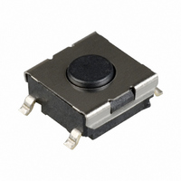
MECHANICAL KEYSWITCH
Manufacturer
Omron
Series
B3FSr
Specifications of B3FS-1000P
Circuit
SPST-NO
Switch Function
Off-Mom
Contact Rating @ Voltage
0.05A @ 24VDC
Actuator Type
Standard
Mounting Type
Surface Mount
Orientation
Vertical
Outline
6.30mm x 6.00mm
Illumination
Non-Illuminated
Operating Force
100gf
Actuator
Flat
Contact Current Rating
50 mAmps at 24 Volts
Ground Terminal
No
Contact Form
SPST - NO
Termination Style
Solder Pad
Mounting Direction
Straight
Body Size
6.3 mm L x 2.6 mm H
Features
Miniature space saving switch, positive click action plus long life equal to no-contact switch
Mounting Style
SMD/SMT
Operating Temperature Range
- 20 C to + 70 C
Contact Rating
50 mAmps at 24 Volts
Contact Configuration
SPST-NO
Contact Voltage Dc Nom
24V
Contact Current Max
50mA
Actuation Type
Top
Switch Terminals
SMD Gull Wing
Circuitry
SPST-NO
Rohs Compliant
Yes
Actuator Style
Flat Plunger
Lead Free Status / RoHS Status
Lead free / RoHS Compliant
Lead Free Status / RoHS Status
Lead free / RoHS Compliant
Other names
B3FS1000P
SW423TR
SW423TR
Available stocks
Company
Part Number
Manufacturer
Quantity
Price

Part Number:
B3FS-1000P
Manufacturer:
OMRON/欧姆龙
Quantity:
20 000


Precautions
B3FS-1050P
B3S
Note:
Standards
Package
Heat resistance
Standards
Package
Heat resistance
Tape drawing direction
Switches with ground terminals are packaged with the
ground terminal on the opposite side of the guide hole.
1.5
8.7
+0.1
0
dia.
0.06
Reel
Reel (made of paper)
7
(22)
1.5
+0.1
12±
0
13 dia.
4±
dia.
Tape drawing direction
Label
0.1
Conforms to JEITA.
1,000 Switches
60 ° C for 24 hours (without deformation)
Conforms to JEITA.
1,000 Switches
50 ° C for 24 hours (without deformation)
0.1
9.4
1.5
12±
2
4±
Tape drawing direction
0.1
Tape drawing direction
0.1
1.75±
0.4
380±2 dia.
7.5
Label
0.1
2
330 dia.
16±
4.7
13 dia.
0.3
1.75
7.5
(8.1)
16
21.5
LEDs (B3J)
Make sure that the polarity of the LEDs is correct. The polarity is
not indicated on the Switch, but the positive pole is located on the
back surface of the Switch on the side without the OMRON mark.
Connect limiting resistors to the LEDs. The Switch does not have
built-in limiting resistors, so satisfy the LED characteristics by
obtaining the limiting resistance according to the following formula
based on the voltage to be used.
Limiting resistance (R)=
0.5
50
30
10
50
40
30
20
10
5
3
1
0
−20
1.5
1.6
(Voltage used (E) – LED forward voltage (VF))
R
0
1.7
E
Green
Yellow
LED forward current (IF)
20
Red
I
V
F
F
Ambient temperature Ta (°C)
1.8
40
Forward voltage V
1.9
Red
Yellow/Green
60
Precautions
2.0
F
2.1
(V)
80
(Ω)
7
Related parts for B3FS-1000P
Image
Part Number
Description
Manufacturer
Datasheet
Request
R

Part Number:
Description:
MECHANICAL KEYSWITCH
Manufacturer:
Omron
Datasheet:

Part Number:
Description:
MECHANICAL KEYSWITCH
Manufacturer:
Omron
Datasheet:

Part Number:
Description:
MECHANICAL KEYSWITCH
Manufacturer:
Omron
Datasheet:
Part Number:
Description:
SWITCH TACTILE SPST-NO .05A SMD
Manufacturer:
Omron
Datasheet:

Part Number:
Description:
SWITCH TACT 6MM 150GF SPST SMD
Manufacturer:
Omron
Datasheet:
Part Number:
Description:
Tactile & Jog Switches 6X6X3.1mm 100gF
Manufacturer:
Omron
Datasheet:

Part Number:
Description:
Mechanical Keyswitch
Manufacturer:
Omron
Datasheet:
Part Number:
Description:
TACTILE SWITCH
Manufacturer:
Omron
Datasheet:
Part Number:
Description:
Tactile Switch
Manufacturer:
Omron
Datasheet:
Part Number:
Description:
Mechanical Keyswitch
Manufacturer:
Omron
Datasheet:
Part Number:
Description:
TACTILE SWITCH
Manufacturer:
Omron
Datasheet:

Part Number:
Description:
Tactile & Jog Switches 12x12mm 4.3mm Height SMT Flat 1.47N Black
Manufacturer:
Omron
Datasheet: