B3J-1100 Omron, B3J-1100 Datasheet - Page 7
B3J-1100
Manufacturer Part Number
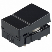
B3J-1100
Description
MECHANICAL KEY SWITCH
Manufacturer
Omron
Series
B3Jr
Type
Keyswitchr
Specifications of B3J-1100
Circuit
SPST-NO
Switch Function
Off-Mom
Contact Rating @ Voltage
0.05A @ 24VDC
Actuator Type
Square Button
Mounting Type
Through Hole
Termination Style
PC Pin
Operating Force
1.27 N
Actuator
Hinged Square
Contact Current Rating
50 mAmps to 24 Volts
Ground Terminal
No
Contact Form
SPST - NO
Mounting Direction
Straight
Features
Tactile switch with integral key cap
Mounting Style
Through Hole
Operating Temperature Range
- 25 C to + 70 C
Contact Rating
50 mAmps to 24 Volts
Contact Configuration
SPST-NO
Contact Voltage Dc Nom
24V
Contact Current Max
50mA
Actuation Type
Top
Switch Terminals
PCB / Push-on
Circuitry
SPST-NO
Rohs Compliant
Yes
Actuator / Cap Color
Black
Lead Free Status / RoHS Status
Lead free / RoHS Compliant
Illumination Type, Color
-
Illumination Voltage (nominal)
-
Lead Free Status / Rohs Status
Lead free / RoHS Compliant
Other names
B3J1100
SW820
Z2177
Z2177
SW820
Z2177
Z2177


Precautions
B3FS-1050P
B3S
Note:
Standards
Package
Heat resistance
Standards
Package
Heat resistance
Tape drawing direction
Switches with ground terminals are packaged with the
ground terminal on the opposite side of the guide hole.
1.5
8.7
+0.1
0
dia.
0.06
Reel
Reel (made of paper)
7
(22)
1.5
+0.1
12±
0
13 dia.
4±
dia.
Tape drawing direction
Label
0.1
Conforms to JEITA.
1,000 Switches
60 ° C for 24 hours (without deformation)
Conforms to JEITA.
1,000 Switches
50 ° C for 24 hours (without deformation)
0.1
9.4
1.5
12±
2
4±
Tape drawing direction
0.1
Tape drawing direction
0.1
1.75±
0.4
380±2 dia.
7.5
Label
0.1
2
330 dia.
16±
4.7
13 dia.
0.3
1.75
7.5
(8.1)
16
21.5
LEDs (B3J)
Make sure that the polarity of the LEDs is correct. The polarity is
not indicated on the Switch, but the positive pole is located on the
back surface of the Switch on the side without the OMRON mark.
Connect limiting resistors to the LEDs. The Switch does not have
built-in limiting resistors, so satisfy the LED characteristics by
obtaining the limiting resistance according to the following formula
based on the voltage to be used.
Limiting resistance (R)=
0.5
50
30
10
50
40
30
20
10
5
3
1
0
−20
1.5
1.6
(Voltage used (E) – LED forward voltage (VF))
R
0
1.7
E
Green
Yellow
LED forward current (IF)
20
Red
I
V
F
F
Ambient temperature Ta (°C)
1.8
40
Forward voltage V
1.9
Red
Yellow/Green
60
Precautions
2.0
F
2.1
(V)
80
(Ω)
7
Related parts for B3J-1100
Image
Part Number
Description
Manufacturer
Datasheet
Request
R

Part Number:
Description:
SWITCH TACT SPST-NO RED LED BLCK
Manufacturer:
Omron
Datasheet:

Part Number:
Description:
MECHANICAL KEY SWITCH
Manufacturer:
Omron
Datasheet:

Part Number:
Description:
MECHANICAL KEY SWITCH
Manufacturer:
Omron
Datasheet:

Part Number:
Description:
MECHANICAL KEY SWITCH
Manufacturer:
Omron
Datasheet:

Part Number:
Description:
MECHANICAL KEY SWITCH
Manufacturer:
Omron
Datasheet:

Part Number:
Description:
MECHANICAL KEY SWITCH
Manufacturer:
Omron
Datasheet:

Part Number:
Description:
Mechanical Keyswitch
Manufacturer:
Omron
Datasheet:

Part Number:
Description:
MECHANICAL KEY SWITCH
Manufacturer:
Omron
Datasheet:
Part Number:
Description:
MECHANICAL KEY SWITCH
Manufacturer:
Omron
Datasheet:
Part Number:
Description:
Mechanical Key Switch
Manufacturer:
Omron
Datasheet:
Part Number:
Description:
MECHANICAL KEY SWITCH
Manufacturer:
Omron
Datasheet:
Part Number:
Description:
MECHANICAL KEY SWITCH
Manufacturer:
Omron
Datasheet:
Part Number:
Description:
MECHANICAL KEY SWITCH
Manufacturer:
Omron
Datasheet:
Part Number:
Description:
MECHANICAL KEY SWITCH
Manufacturer:
Omron
Datasheet:
Part Number:
Description:
MECHANICAL KEY SWITCH
Manufacturer:
Omron
Datasheet: