B3J-6100 Omron, B3J-6100 Datasheet

MECHANICAL KEY SWITCH

B3J-6100

Manufacturer Part Number
B3J-6100
Description
MECHANICAL KEY SWITCH
Manufacturer
Omron
Series
B3Jr
Type
Keyswitch, Illuminatedr
Datasheets

Specifications of B3J-6100

Circuit
SPST-NO
Switch Function
Off-Mom
Contact Rating @ Voltage
0.05A @ 24VDC
Actuator Type
Square Button
Illumination Type, Color
LED, Red/ Green
Illumination Voltage (nominal)
2.0, 2.1 VDC
Mounting Type
Through Hole
Termination Style
PC Pin
Operating Force
130 g +/- 50 g
Actuator
Key Cap
Contact Current Rating
1 mAmp to 50 mAmps at 5 Volts to 24 Volts
Contact Form
SPST - NO
Body Size
18 mm L x 12 mm W x 10.3 mm H
Color
Black
Features
Tactile Switch with Integral Key Cap
Mounting Style
PCB
Operating Temperature Range
- 25 C to + 70 C
Contact Rating
1 mAmp to 50 mAmps at 5 Volts to 24 Volts
Contact Configuration
SPST-NO
Contact Voltage Dc Nom
24V
Contact Current Max
50mA
Actuation Type
Top
Switch Terminals
PCB / Push-on
Circuitry
SPST-NO
Rohs Compliant
Yes
Actuator / Cap Color
Black
Lead Free Status / RoHS Status
Lead free / RoHS Compliant
Lead Free Status / RoHS Status
Lead free / RoHS Compliant
Other names
B3J6100
SW826
Z2183
Z2183
Hinged Design Developed through
Ergonomics
Ordering Information
Specifications
Light gray
Black
Orange
Yellow
Blue
Switching capacity
Ambient temperature
Ambient humidity
Contact configuration
Contact resistance
Insulation resistance
Dielectric strength
Bounce time
Vibration resistance
Shock resistance
Life expectancy
Weight
hinged button
Tactile Switch (Hinged Type)
Quick, superior snap action through hook-type
hinge construction.
Available with 1 or 2 LEDs or without LEDs.
The hinge button is available in a wide variety of
colors (five standard colors).
Ratings/Characteristics
Color of
B3J-1000
B3J-1100
B3J-1200
B3J-1300
B3J-1400
No LED
B3J-2000
B3J-2100
B3J-2200
B3J-2300
B3J-2400
Red
1 to 50 mA, 5 to 24 VDC (resistive load)
–25 ° C to 70 ° C (with no icing)
35% to 85%
SPST-NO
100 m W max. (rated: 1 mA, 5 VDC)
100 M W min. (at 250 VDC)
500 VAC, 50/60 Hz for 1 min
5 ms max.
Malfunction: 10 to 55 Hz, 1.5-mm double amplitude
Destruction: 1,000 m/s
Malfunction: 100 m/s
3,000,000 operations min.
Approx. 1.5 to 1.7 g
B3J-3000
B3J-3100
B3J-3200
B3J-3300
B3J-3400
One LED
Yellow
2
{approx. 10G} max.
2
{approx. 100G} max.
B3J-4000
B3J-4100
B3J-4200
B3J-4300
B3J-4400
Green
B3J-5000
B3J-5100
B3J-5200
B3J-5300
B3J-5400
Red/Yellow
Two LEDs (left and right)
B3J-6000
B3J-6100
B3J-6200
B3J-6300
B3J-6400
Red/Green
B3J
B3J-7000
B3J-7100
B3J-7200
B3J-7300
B3J-7400
Yellow/Green
33

Related parts for B3J-6100

B3J-6100 Summary of contents

Page 1

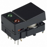
... Destruction: 1,000 m/s {approx. 100G} max. 2 Malfunction: 100 m/s {approx. 10G} max. 3,000,000 operations min. Approx. 1.5 to 1.7 g B3J Two LEDs (left and right) Red/Yellow Red/Green Yellow/Green B3J-5000 B3J-6000 B3J-7000 B3J-5100 B3J-6100 B3J-7100 B3J-5200 B3J-6200 B3J-7200 B3J-5300 B3J-6300 B3J-7300 B3J-5400 B3J-6400 B3J-7400 33 ...

Page 2

... Since the built-in LED does not contain any limiting resistors, externally connect limiting resistors within the limits shown in the above table. Engineering Data Operating Force vs. Stroke (Typical) 1.76 {180} 1.66 {170} 1.56 {160} 1.37 {140} 1.17 {120} 0.98 {100} 0.78 {80} 0.58 {60} 0.39 {40} 0.19 {20} Stroke S (mm Red 2.0 2 Yellow Green 2 B3J ...

Page 3

... LED Types B3J-2@00, -3@00, -4@00 18±0.2 12±0.2 9±0.1 2 LED Types B3J-5@00, -6@00, -7@00 18±0.2 12±0.2 9±0.1 Precautions Be sure to read the precautions common to all Tactile Switches on pages for correct use. PCB Mounting (Top View) Two, 1.8±0.05 dia.* (For positioning boss) 12 12.5± ...

Page 4

... B3J ALL DIMENSIONS SHOWN ARE IN MILLIMETERS. To convert millimeters into inches, multiply by 0.03937. To convert grams into ounces, multiply by 0.03527. Cat. No. A071-E1-04 36 B3J ...

Page 5

... Do not solder the Switch more than twice, including rectification soldering. An interval of five minutes is required between the first and second soldering. 2. Automatic Soldering Baths (B3F, B3W, B3WN, B3M, B3J) Soldering temperature: 260 ° C max. Soldering time max. for a 1.6-mm thick single-side PCB Preheating temperature: 100° ...

Page 6

... Switch through respira- tion as the Switch cools. Wait for at least three minutes after sol- dering before cleaning washable models. Do not use Sealed Switches while submersed in water or in loca- tions exposed to water. Switch Packaging (Taping Specification Models) 1 ...

Page 7

... Note: Switches with ground terminals are packaged with the ground terminal on the opposite side of the guide hole. LEDs (B3J) Make sure that the polarity of the LEDs is correct. The polarity is not indicated on the Switch, but the positive pole is located on the back surface of the Switch on the side without the OMRON mark. ...

Related keywords