B3W-1152 Omron, B3W-1152 Datasheet - Page 3
B3W-1152
Manufacturer Part Number
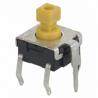
B3W-1152
Description
Pushbutton Switch,STRAIGHT,SPST,OFF-(ON),PC TAIL W/RETNN Terminal,PCB Hole Count:5
Manufacturer
Omron
Series
B3Wr
Type
Tactiler
Specifications of B3W-1152
Circuit
SPST-NO
Switch Function
Off-Mom
Contact Rating @ Voltage
0.05A @ 24VDC
Actuator Type
Plunger for Cap
Mounting Type
Through Hole
Orientation
Vertical
Outline
6.60mm x 6.00mm
Illumination
Non-Illuminated
Operating Force
230gf
Pole Throw Configuration
SPST
Switch Function Configuration
N.O.
Actuator Style
Projected Plunger
Actuator Color
Yellow
Actuator Length (mm)
3.9mm
Current Rating (max)
0.05A
Illumination Type
Not Required
Voltage Rating (vdc)
24V
Ground Terminal
Yes
Mechanical Life
1000000
Product Length (mm)
6mm
Product Depth (mm)
6.6mm
Product Height (mm)
7.3mm
Operating Temp Range
-25C to 70C
Body Orientation
Straight
Mounting Style
Through Hole
Terminal Type
PC Pins
Actuator
Top
Contact Rating
50 mAmps at 24 Volts
Contact Form
SPST - NO
Termination Style
Solder Pin
Body Size
6.6 mm L x 6 mm W x 3.65 mm H
Features
Features Sealed Construction for Automatic Soldering
Operating Temperature Range
- 25 C to + 70 C
Application
Audio, office and communications equipment, measuring instruments, industrial robots, VCRs, TVs, and vending machines
Current, Rating
50 mA
Dielectric Strength
500 VAC
Mounting Hole Size
1 mm
Number Of Poles
1
Special Features
Projected Plunger
Termination
Through Hole
Voltage, Rating
24 VDC
Contact Configuration
SPST-NO
Contact Voltage Dc Nom
24V
Contact Current Max
50mA
Actuation Type
Top
Switch Terminals
PCB / Push-on
Circuitry
SPST-NO
Rohs Compliant
Yes
Lead Free Status / RoHS Status
Lead free / RoHS Compliant
Lead Free Status / RoHS Status
Lead free / RoHS Compliant
Other names
B3W-1152
B3W-1152BYOMZ
B3W1152
SW975
B3W-1152BYOMZ
B3W1152
SW975


B3W
Dimensions
Note:
■
20
Flat Plunger Type
(without Ground
Terminal)
B3W-1000
B3W-1002
Projected Plunger Type
(without Ground
Terminal)
B3W-1050
B3W-1052
6 × 6 mm Models
PCB Mounting (Top View)
(Single-sided PCB, t=1.6)
PCB Mounting (Top View)
(Single-sided PCB, t=1.6)
1. All units are in millimeters unless otherwise indicated. Unless otherwise specified, a tolerance of ± 0.4 mm applies to all dimen-
2. No terminal numbers are indicated on the Switches. The numbers used for terminals in the following graphics are
sions.
indicated in the “Bottom View” diagram below. In this diagram, the Switch is rotated so that the terminals are on the
right and left-hand sides, and the OMRON logo appears the right way up.
6.5
6.5
±0.1
±0.1
7.3
±0.2
6.6
4.3
6.6
1.8
4.3
3.5
3.5
±0.2
±0.2
±0.2
±0.1
±0.2
Four, 1
Four, 1
4.5
4.5
±0.1
±0.1
2.4 × 2.4
±0.05
±0.05
6.5
7.7
6
6.5
7.7
6
±0.2
±0.2
±0.5
±0.5
dia.
±0.5
±0.5
dia.
Terminal Arrangement
/Internal Connections
(Top View)
±0.1
Terminal Arrangement
/Internal Connections
(Top View)
4
2
3.3 dia.
4
2
3.3 dia.
0.3
4.5
0.3
4.5
(1.8)
3.4
(1.8)
3.4
±0.2
±0.2
0.7
3
1
0.7
3
1
0.7
0.7
Flat Plunger Type
(with Ground
Terminal)
B3W-1100
B3W-1102
Projected Plunger Type
(with Ground
Terminal)
B3W-1150
B3W-1152
4.1
±0.1
4.1
PCB Mounting (Top View)
(Single-sided PCB, t=1.6)
PCB Mounting (Top View)
(Single-sided PCB, t=1.6)
±0.1
7.3
6.5
±0.2
6.6
4.3
±0.1
6.5
6.6
1.8
4.3
3.5
3.5
±0.2
±0.2
±0.1
±0.2
±0.1
±0.2
0.7
0.7
2.4 × 2.4
1.5
6.5
7.7
Five, 1
6.5
7.7
6
4.5
6
±0.2
±0.2
±0.5
±0.5
Five, 1
±0.5
±0.5
±0.1
4.5
±0.1
±0.05
1.5
±0.1
±0.05
Terminal Arrangement
/Internal Connections
(Top View)
dia.
3.3 dia.
3.3 dia.
0.3
4.5
0.3
Terminal Arrangement
/Internal Connections
(Top View)
dia.
4.5
(1.8)
(1.8)
3.4
3.4
±0.2
±0.2
4
2
4
2
0.25
5
0.25
0.7
0.7
(Bottom View)
2
4
3
1
0.7
3
1
B3W
0.7
1
3
Related parts for B3W-1152
Image
Part Number
Description
Manufacturer
Datasheet
Request
R

Part Number:
Description:
SWITCH TACT ILLUM SPST-NO YELLOW
Manufacturer:
Omron
Datasheet:

Part Number:
Description:
SWITCH TACT ILLUM SPST-NO YELLOW
Manufacturer:
Omron
Datasheet:

Part Number:
Description:
SWITCH TACT ILLUM SPST-NO GREEN
Manufacturer:
Omron
Datasheet:

Part Number:
Description:
SWITCH TACT ILLUM SPST-NO RED
Manufacturer:
Omron
Datasheet:

Part Number:
Description:
SWITCH TACT ILLUM SPST-NO RED
Manufacturer:
Omron
Datasheet:
Part Number:
Description:
Sw.Red&HB Green 2LED Trans.Cap
Manufacturer:
Omron
Datasheet:

Part Number:
Description:
Manual Switch
Manufacturer:
Omron
Datasheet:
Part Number:
Description:
Manual Switch
Manufacturer:
Omron
Datasheet:
Part Number:
Description:
Manual Switch
Manufacturer:
Omron
Datasheet:
Part Number:
Description:
Manual Switch
Manufacturer:
Omron
Datasheet:
Part Number:
Description:
Manual Switch
Manufacturer:
Omron
Datasheet:
Part Number:
Description:
Manual Switch
Manufacturer:
Omron
Datasheet:
Part Number:
Description:
Manual Switch
Manufacturer:
Omron
Datasheet:
Part Number:
Description:
Manual Switch
Manufacturer:
Omron
Datasheet:
Part Number:
Description:
Manual Switch
Manufacturer:
Omron
Datasheet: