D2HW-BR232M Omron, D2HW-BR232M Datasheet - Page 5
D2HW-BR232M
Manufacturer Part Number
D2HW-BR232M
Description
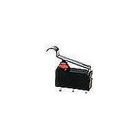
SUBMINIATURE BASIC SWITCH
Manufacturer
Omron
Series
D2HWr
Datasheet
1.D2HW-A201D.pdf
(10 pages)
Specifications of D2HW-BR232M
Circuit
SPST-NC
Switch Function
On-Mom
Contact Rating @ Voltage
2A @ 12VDC
Actuator Type
Lever, Simulated Roller
Mounting Type
Chassis Mount
Termination Style
Wire Leads
Operating Force
66gf
Contact Form
SPST - NC
Contact Rating
1 Amp at 24 Volts
Actuator
Simulated Roller Lever
Lead Free Status / RoHS Status
Lead free / RoHS Compliant
Lead Free Status / RoHS Status
Lead free / RoHS Compliant
Other names
D2HWBR232M


Dimensions
■ Mounting Structure and Reference Positions for Operating Characteristics
Note: 1. All units are in millimeters unless otherwise indicated.
■ Terminals
Lead Wires on Left-side
Reference
position
Models without Posts
D2HW-A@
PCB Cutout Dimensions (Reference)
Straight PCB Terminals
Angled terminal directions are shown below.
Left-angled terminal
2. Dimensions not indicated in the diagrams have a tolerance of ±0.2 mm
3. The reference positions used for FP, OP, and TTP values are as shown below for each type of mounting.
Three, 1
+0.1
0
dia. hole
Three-0.6
1.7 dia.
Right-angled terminal
(13.3)
2.4
(depth: 5 mm min.)
+0.1
0
Reference
position
dia. hole
Note: UL1007 AWG24 wires are used for UL/CSA approved models.
Models with Posts
D2HW-B@
(12)
2.4
(depth: 5 mm min.)
(12)
Mounting Hole Dimensions (Reference) Mounting Hole Dimensions (Reference)
Lead Wires on Right-side
1.7 dia.
+0.1
0
Angled PCB Terminals
PCB Cutout Dimensions (Reference)
dia. hole
(13.3)
2.6
Three-0.6
Sealed Subminiature Snap Action Switch
Three, 1
2.6
(3.1)
+0.1
0
dia. hole
M3-screw Mounting Models
D2HW-C@
Reference
position
(12)
Lead Wires Downwards
3
(depth: 1.5 mm min.)
3
+0.1
−0.1
0
0
Solder Terminals
dia.
dia. hole
M3 tap
Three-2
COM AVSS 0.5
(Black)
NO AVSS 0.5 (Blue)
NC AVSS 0.5 (Red)
See Note
3.3±0.15 dia.
3.5
D2HW
185
Related parts for D2HW-BR232M
Image
Part Number
Description
Manufacturer
Datasheet
Request
R

Part Number:
Description:
SUBMINIATURE BASIC SWITCH
Manufacturer:
Omron
Datasheet:
Part Number:
Description:
SUBMINIATURE BASIC SWITCH
Manufacturer:
Omron
Datasheet:
Part Number:
Description:
SUBMINIATURE BASIC SWITCH
Manufacturer:
Omron
Datasheet:
Part Number:
Description:
SUBMINIATURE BASIC SWITCH
Manufacturer:
Omron
Datasheet:
Part Number:
Description:
SUBMINIATURE BASIC SWITCH
Manufacturer:
Omron
Datasheet:
Part Number:
Description:
SUBMINIATURE BASIC SWITCH
Manufacturer:
Omron
Datasheet:
Part Number:
Description:
SUBMINIATURE BASIC SWITCH
Manufacturer:
Omron
Datasheet:
Part Number:
Description:
SWITCH SUBMINIATURE BASIC SPDT
Manufacturer:
Omron
Datasheet:
Part Number:
Description:
SWITCH SUBMINIATURE BASIC SPDT
Manufacturer:
Omron
Datasheet:
Part Number:
Description:
SWITCH SUBMINI BASIC SPDT-NO
Manufacturer:
Omron
Datasheet:
Part Number:
Description:
SWITCH SUBMINIATURE BASIC SPDT
Manufacturer:
Omron
Datasheet:
Part Number:
Description:
SWITCH SUBMINI BASIC SPST-NO
Manufacturer:
Omron
Datasheet:

Part Number:
Description:
SWITCH SUBMINI BASIC SPDT-NO
Manufacturer:
Omron
Datasheet:

Part Number:
Description:
SWITCH BASIC SPDT 2A SEALED
Manufacturer:
Omron
Datasheet:

Part Number:
Description:
SWITCH LEVER SPDT 2A SEALED
Manufacturer:
Omron
Datasheet: