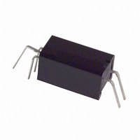
EE-SY313 Omron, EE-SY313 Datasheet - Page 2

EE-SY313
Manufacturer Part Number
EE-SY313
Description
PHOTOMICROSENSOR W/LENS
Manufacturer
Omron
Datasheet
1.EE-SY413.pdf
(3 pages)
Specifications of EE-SY313
Maximum Operating Temperature
+ 65 C
Minimum Operating Temperature
- 40 C
Wavelength
920 nm
Sensing Method
Reflective
Output Collector Emitter Voltage (detector)
28 V
Maximum Reverse Voltage (emitter)
4 V
Maximum Collector Current (detector)
16 mA
Output Device
Photologic, Open Collector
Power Dissipation
250 mW
Lead Free Status / RoHS Status
Lead free / RoHS Compliant
Lead Free Status / RoHS Status
Lead free / RoHS Compliant
Available stocks
Company
Part Number
Manufacturer
Quantity
Price
Company:
Part Number:
EE-SY313/EE-SY413
Manufacturer:
SHARP
Quantity:
1
■ Engineering Data
Note: The values in the parentheses apply to the EE-SY413.
Note: 1. With incident light" denotes the condition whereby
Forward Current vs. Collector
Dissipation Temperature Rating
LED Current vs. Ambient
Temperature Characteristics
(Typical)
Current Consumption vs. Supply
Voltage (Typical)
Ambient temperature Ta ( C)
Ambient temperature Ta ( C)
3. Hysteresis denotes the difference in forward LED
2. Sensing object: White paper with a reflection factor of
I
FT
Supply voltage V
the light reflected by white paper with a reflection
factor of 90% at a sensing distance of 4.4 mm is
received by the photo IC when the forward current (I
of the LED is 20 mA.
I
current value, expressed in percentage, calculated
from the respective forward LED currents when the
photo IC is turned from ON to OFF and when the
photo IC is turned from OFF to ON.
90% at a sensing distance of 4.4 mm.
FT
OFF (I
ON (I
FT
FT
ON)
OFF)
Ta = 25 C
I
F
= 0 mA (15 mA)
V
R
CC
L
CC
= 330
= 5 V
(V)
Forward Current vs. Forward
Voltage Characteristics (Typical)
Low-level Output Voltage vs.
Output Current (Typical)
Response Delay Time vs. Forward
Current (Typical)
V
R
Ta = 25 C
EE-SY313/-SY413
CC
L
Forward current I
Output current I
= 330
= 5 V
Forward voltage V
F
)
Ta = 25 C
Ta = 70 C
Ta = 30 C
5. The following illustrations show the definition of response delay
V
(EE-SY3@@)
V
(EE-SY4@@)
4. The value of the response frequency is measured by rotating
t
OUT
OUT
PHL
time. The value in the parentheses applies to the EE-SY413.
the disk as shown below.
(t
PLH
Ta = 25 C
Output
V
I
Input
F
CC
)
= 0 mA (20 mA)
= 5 V
15 mm
t
C
PLH
F
(mA)
(t
(mA)
PHL
F
(t
)
(V)
200 mm dia.
EE-SY313
PLH
)
15 mm
Photomicrosensor (Reflective)
15 mm
LED Current vs. Supply Voltage
(Typical)
Low-level Output Voltage vs.
Ambient Temperature
Characteristics (Typical)
Sensing Position Characteristics
(Typical)
(t
PHL
)
Sensing object: White
paper with a reflection
factor of 90%
I
V
Ta = 25 C
Ambient temperature Ta ( C)
F
Output
I
CC
= 20 mA
I
OL
Input
FT
Supply voltage V
= 5 V
= 16 mA
OFF (I
Distance d
I
FT
I
OL
4.4 mm
ON (I
FT
= 5 mA
Operate
EE-SY413
ON)
(t
Release
PHL
FT
)
V
OFF)
I
F
CC
1
= 0 mA (20 mA)
(mm)
= 5 V
CC
Ta = 25 C
R
L
(V)
= 1 k
(t
PLH
)
173


