G3NA-210B-DC5-24 Omron, G3NA-210B-DC5-24 Datasheet - Page 5
G3NA-210B-DC5-24
Manufacturer Part Number
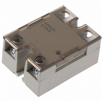
G3NA-210B-DC5-24
Description
SOLID STATE RELAY
Manufacturer
Omron
Series
G3NAr
Datasheets
1.Y92B-A150N.pdf
(18 pages)
2.G3NA-610B_AC100-240.pdf
(14 pages)
3.G3NA-210B-AC100-120.pdf
(16 pages)
Specifications of G3NA-210B-DC5-24
Control Voltage Range
5 VDC to 24 VDC
Load Current
10A
Circuit
SPST-NO (1 Form A)
Output Type
AC, Zero Cross
Voltage - Input
5 ~ 24VDC
Voltage - Load
19 ~ 264 V
Mounting Type
Chassis Mount
Termination Style
Screw Terminal
Package / Case
Hockey Puck
Load Voltage Rating
264 V
Load Current Rating
10 A
Contact Form
1 Form A
Output Device
Triac
Input To Output Isolation Method
Phototriac
Relay Type
General Purpose Hockey Puck
Operating Voltage Range
19VAC To 264VAC
Isolation Voltage
2500VAC
Control Voltage Type
DC
Relay Terminals
Screw
Load Voltage Max
240VAC
Load Voltage Min
24VAC
Rohs Compliant
Yes
Lead Free Status / RoHS Status
Lead free / RoHS Compliant
On-state Resistance
-
Lead Free Status / Rohs Status
Lead free / RoHS Compliant
Other names
G3NA210BDC524
Z918
Z918


Heat Sinks
Y92B-N50 Heat Sink (for max. 10 A load current)
Type G3NA-610B is recommended for max. 10 A with this heat sink.
For upright standing to the ground, a 30% derating of the load current is required (from the Load Current vs. Ambient Temperature graphs).
Y92B-N100 Heat Sink (for max. 20 A load current)
The orientation indicated by the external dimensions is not the correct mounting orientation. When opening mounting holes, refer to the
mounting hole dimensions.
Type G3NA-625B is recommended for max. 25 A and G3NA-650B for max. 40 A with this heat sink.
For upright standing to the ground, a 30% derating of the load current is required (from the Load Current vs. Ambient Temperature graphs).
Type G3NA-625B is recommended for 20 A with this heat sink.
For upright standing to the ground, a 30% derating of the load current is required (from the Load Current vs. Ambient Temperature graphs).
The orientation indicated by the external dimensions is not the correct mounting orientation. When opening mounting holes, refer to the
mounting hole dimensions.
Y92B-N150 Heat Sink (for max. 40 A load current)
The orientation indicated by the external dimensions is not the correct mounting orientation. When opening mounting holes, refer to the
mounting hole dimensions.
35
35
30.5±0.3
4.6 dia.
30.5±0.3
35
4.6 dia.
4.6 dia.
77 max.
90±0.3
Two, M3 holes
100 max.
90±0.3
100 max.
77 max.
47.6
56±0.3
100 max.
Two, M3 holes
77 max.
90±0.3
47.6
47.6
Three,
M4 holes
Two, M4
holes
Two, M4 holes
100 max.
71 max.
5.6
5.6
5.6
44 max.
30
30
30
Solid State Relays (600 VAC Models)
Two, 3.2-dia. holes
Two, 3.2-dia. holes
Two, 3.2-dia. holes
28
30
28
5
100 max.
100 max.
5
51 max.
5
6
13
13
47 max.
4.5
104 max.
75 max.
4.5
4.5
Weight: approx. 400 g
Mounting Holes
Mounting Holes
Weight: approx. 560 g
Weight: approx. 200 g
Mounting Holes
35±0.2
35±0.2
Two, 4.4-dia.
or M4 holes
Two, 4.4-dia.
or M4 holes
G3NA-6
90±0.4
90±0.4
Two, 4.4-dia.
or M4 holes
471
Related parts for G3NA-210B-DC5-24
Image
Part Number
Description
Manufacturer
Datasheet
Request
R

Part Number:
Description:
RELAY SSR 10A 200-240VAC ZERO
Manufacturer:
Omron
Datasheet:

Part Number:
Description:
RELAY SSR 120VAC@10A ZERO AC IN
Manufacturer:
Omron
Datasheet:

Part Number:
Description:
SOLID STATE RELAY/TUV MARKINGS
Manufacturer:
Omron
Datasheet:
Part Number:
Description:
RELAY SSR 120VAC@10A ZERO AC IN
Manufacturer:
Omron
Datasheet:

Part Number:
Description:
Solid State Relays SS Relay 10 A 5 to 24 VDC
Manufacturer:
Omron
Datasheet:

Part Number:
Description:
SSR, PANEL MOUNT, 264VAC, 24VDC, 10A
Manufacturer:
Omron
Datasheet:

Part Number:
Description:
SSR, 10A
Manufacturer:
Omron
Datasheet:


Part Number:
Description:
RELAY; SSR; GEN PURP; CUR-RTG 10A; CTRL-V 5-24DC; VOL-RTG 24-240AC; 4 PIN
Manufacturer:
Omron Automation
Datasheet:
Part Number:
Description:
RELAY; SSR; GEN PURP; CUR-RTG 10A; CTRL-V 100-120AC; VOL-RTG 24-240AC; 4 PIN
Manufacturer:
Omron Automation
Datasheet:
Part Number:
Description:
RELAY; SSR; GEN PURP; CUR-RTG 10A; CTRL-V 200-240AC; VOL-RTG 24-240AC; 4 PIN
Manufacturer:
Omron Automation
Datasheet:
Part Number:
Description:
G6S-2GLow Signal Relay
Manufacturer:
Omron Corporation
Datasheet:
Part Number:
Description:
Compact, Low-cost, SSR Switching 5 to 20 A
Manufacturer:
Omron Corporation
Datasheet: