G3VM-351GL Omron, G3VM-351GL Datasheet - Page 2
G3VM-351GL
Manufacturer Part Number
G3VM-351GL
Description
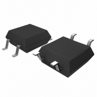
MOSFET SOP Relay
Manufacturer
Omron
Series
G3VMr
Datasheets
1.G3VM-2FL.pdf
(6 pages)
2.G3VM-2FL.pdf
(4 pages)
3.G3VM-351GL.pdf
(4 pages)
4.G3VM-351G1.pdf
(4 pages)
Specifications of G3VM-351GL
Circuit
SPST-NO (1 Form A)
Output Type
AC, DC
On-state Resistance
35 Ohm
Load Current
110mA
Voltage - Input
1.15VDC
Voltage - Load
0 ~ 350 V
Mounting Type
Surface Mount
Termination Style
Gull Wing
Package / Case
4-SOP
Control Voltage Range
1 V to 1.3 V
Load Voltage Rating
350 V
Off State Leakage Current (max)
1 uA
Load Current Rating
120 mA
Contact Form
1 Form A
Output Device
MOSFET
Mounting Style
SMD/SMT
Relay Type
MOSFET Relay
Turn-on Switching
FET
Input Type
DC
Input Voltage (max)
1.3V
Output Voltage (max)
350V
Input Current (max)
50mA
Output Current
120mA
Package Type
SOP
Pin Count
4
Mounting
Surface Mount
Operating Temp Range
-40C to 85C
Operating Temperature Classification
Industrial
Rad Hardened
No
Lead Free Status / RoHS Status
Lead free / RoHS Compliant
Lead Free Status / RoHS Status
Lead free / RoHS Compliant
Other names
G3VM351GL
Z2457
Z2457
Available stocks
Company
Part Number
Manufacturer
Quantity
Price
Company:

Part Number:
G3VM-351GL
Manufacturer:
Panasonic
Quantity:
12 000
Company:
Part Number:
G3VM-351GL(TR)
Manufacturer:
FUJITSU
Quantity:
12 000


■ Absolute Maximum Ratings (Ta = 25°C)
■ Electrical Characteristics (Ta = 25°C)
■ Recommended Operating Conditions
Use the G3VM under the following conditions so that the Relay will operate properly.
186
Input
Output Load voltage (AC peak/DC) V
Dielectric strength between input and
output (See note 1.)
Operating temperature
Storage temperature
Soldering temperature (10 s)
Input
Output Maximum resistance with output ON
Limit current
Capacity between I/O terminals
Insulation resistance
Turn-ON time
Turn-OFF time
Load voltage (AC peak/DC)
Operating LED forward current
Continuous load current (AC peak/DC) I
Operating temperature
LED forward voltage
Reverse current
Capacity between terminals
Trigger LED forward current
Current leakage when the relay is open I
Capacity between terminals
LED forward current
Repetitive peak LED
forward current
LED forward current
reduction rate
LED reverse voltage
Connection temperature
Continuous load current
ON current reduction rate
Connection temperature
MOS FET Relays
Item
Item
Item
I
I
Δ I
V
Δ I
V
---
Symbol
T
I
T
T
T
F
FP
O
a
V
I
T
j
OFF
j
stg
R
I-O
F
O
a
F
ON
DD
/°C
Symbol
/°C −1.2
G3VM-351GL
50
1
−0.5
6
125
350
120
125
1,500
−40 to +85
−55 to +125 °C
260
V
I
C
I
R
C
I
C
R
t
t
Symbol
R
FT
LEAK
LIM
ON
OFF
F
Rating
T
ON
OFF
I-O
I-O
---
5
---
− 20
Minimum
1.0
---
---
---
---
---
---
150
---
1,000
---
---
Mini-
mum
mA
A
mA/°C
V
°C
V
mA
mA/°C
°C
V
°C
°C
rms
Unit
1.15
---
30
1
15
0.0005
70
---
0.8
---
0.3
0.1
Typical
---
7.5
---
---
100 μs pulses, 100 pps
T
T
AC for 1 min
With no icing or condensation
With no icing or condensation
10 s
a
a
Measurement Conditions
≥ 25°C
≥ 25°C
Typical
1.3
10
---
3
35
1.0
---
300
---
---
1.0
1.0
Maxi-
mum
280
25
100
65
V
μA
pF
mA
Ω
μA
pF
mA
pF
MΩ
ms
ms
Maximum
Unit
I
V
V = 0, f = 1 MHz
I
I
V
V = 0, f = 1MHz
I
t = 5 ms
f = 1 MHz, V
V
R
I
V
F
O
F
F
F
R
OFF
I-O
oH
DD
= 10 mA
= 5 mA, I
= 5 mA, V
= 5 mA, R
= 120 mA
= 6 V
= 500 VDC,
= 20 V (See note 2.)
≤ 60%
Measurement
= 350 V
V
mA
mA
°C
conditions
Note:
Unit
O
DD
L
s
= 120 mA
= 200 Ω,
= 0 V
= 5 V,
1. The dielectric strength between the input and
output was checked by applying voltage be-
tween all pins as a group on the LED side and
all pins as a group on the light-receiving side.
Note:
2. Turn-ON and Turn-OFF
V
I
F
OUT
I
F
Times
1
2
1
2
t
ON
10%
4
3
4
3
AC/DC
Load
R
L
90%
t
OFF
V
V
DD
OUT
Related parts for G3VM-351GL
Image
Part Number
Description
Manufacturer
Datasheet
Request
R

Part Number:
Description:
RELAY SSR SPST 120MA 4-SOP
Manufacturer:
Omron
Datasheet:

Part Number:
Description:
SSR, MOSFET, 350V, 120mA
Manufacturer:
Omron
Datasheet:

Part Number:
Description:
RELAY SSR SPST 120MA 6-SOP
Manufacturer:
Omron
Datasheet:

Part Number:
Description:
RELAY SSR SPST 120MA 4-DIP
Manufacturer:
Omron
Datasheet:

Part Number:
Description:
RELAY SSR SPST 120MA 4-SMT
Manufacturer:
Omron
Datasheet:

Part Number:
Description:
RELAY SSR DPST 120MA 8-SMT
Manufacturer:
Omron
Datasheet:

Part Number:
Description:
RELAY SSR SPST-NO 350VAC 4SMD
Manufacturer:
Omron
Datasheet:

Part Number:
Description:
RELAY SSR SPST 400V 120MA 4SMT
Manufacturer:
Omron
Datasheet:

Part Number:
Description:
RELAY SSR SPST-NO 350VAC 6DIP
Manufacturer:
Omron
Datasheet:
Part Number:
Description:
RELAY SSR SPST 400V 120MA 4DIP
Manufacturer:
Omron
Datasheet:

Part Number:
Description:
G6S-2GLow Signal Relay
Manufacturer:
Omron Corporation
Datasheet:
Part Number:
Description:
Compact, Low-cost, SSR Switching 5 to 20 A
Manufacturer:
Omron Corporation
Datasheet:
Part Number:
Description:
Manufacturer:
Omron Corporation
Datasheet: