G3VM-61E1(TR) Omron, G3VM-61E1(TR) Datasheet - Page 3
G3VM-61E1(TR)
Manufacturer Part Number
G3VM-61E1(TR)
Description
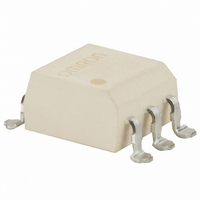
MOSFET SMT Tape And Reel Relay
Manufacturer
Omron
Series
G3VMr
Datasheets
1.G3VM-2FL.pdf
(6 pages)
2.G3VM-2FL.pdf
(4 pages)
3.G3VM-61E1TR.pdf
(4 pages)
4.G3VM-61E1.pdf
(4 pages)
Specifications of G3VM-61E1(TR)
Circuit
SPST-NO (1 Form A)
Output Type
AC, DC
On-state Resistance
2 Ohm
Load Current
500mA
Voltage - Input
1.15VDC
Voltage - Load
0 ~ 60 V
Mounting Type
Surface Mount
Termination Style
Gull Wing
Package / Case
6-SMD (300 mil)
Control Voltage Range
1 V to 1.3 V
Load Voltage Rating
60 V
Off State Leakage Current (max)
1 uA
Load Current Rating
500 mA
Contact Form
1 Form A
Output Device
MOSFET
Mounting Style
SMD/SMT
Relay Type
MOSFET Relay
Turn-on Switching
FET
Lead Free Status / RoHS Status
Lead free / RoHS Compliant
Lead Free Status / RoHS Status
Lead free / RoHS Compliant
Other names
G3VM61E1TR


G3VM Series
Common Precautions
Typical Relay Driving Circuit Examples
Use the following formula to obtain the LED current limiting resis-
tance value to assure that the relay operates accurately.
Use the following formula to obtain the LED forward voltage value
to assure that the relay releases accurately.
4
Be sure to turn OFF the power when wiring the Relay, other-
wise an electric shock may be received.
Do not touch the charged terminals of the SSR, otherwise an
electric shock may be received.
Do not apply overvoltage or overcurrent to the I/O circuits of the
SSR, otherwise the SSR may malfunction or burn.
Be sure to wire and solder the Relay under the proper soldering
conditions, otherwise the Relay in operation may generate ex-
cessive heat and the Relay may burn.
!WARNING
!WARNING
!Caution
!Caution
C-MOS
Transistor
10 to 100 kΩ
R
V
1
F (OFF)
=
V
= V
CC
5 to 20 mA
− V
CC
− V
OL
− V
OH
F
< 0.8 V
(ON)
Load
Load
Protection from Surge Voltage on the Input
Terminals
If any reversed surge voltage is imposed on the input terminals,
insert a diode in parallel to the input terminals as shown in the fol-
lowing circuit diagram and do not impose a reversed voltage value
of 3 V or more.
Surge Voltage Protection Circuit Example
Protection from Spike Voltage on the Output
Terminals
If a spike voltage exceeding the absolute maximum rated value is
generated between the output terminals, insert a C-R snubber or
clamping diode in parallel to the load as shown in the following
circuit diagram to limit the spike voltage.
Spike Voltage Protection Circuit Example
Unused Terminals (6-pin models only)
Terminal 3 is connected to the internal circuit. Do not connect
anything to terminal 3 externally.
Pin Strength for Automatic Mounting
In order to maintain the characteristics of the relay, the force
imposed on any pin of the relay for automatic mounting must not
exceed the following.
In direction A: 1.96 N
In direction B: 1.96 N
G3VM Series
Related parts for G3VM-61E1(TR)
Image
Part Number
Description
Manufacturer
Datasheet
Request
R

Part Number:
Description:
MOSFET SMT Relay
Manufacturer:
Omron
Datasheet:
Part Number:
Description:
MOSFET Tape And Reel Relay
Manufacturer:
Omron
Datasheet:

Part Number:
Description:
RELAY SSR SPST 150MA 4-SOP
Manufacturer:
Omron
Datasheet:

Part Number:
Description:
RELAY SSR SPST 120MA 4-SOP
Manufacturer:
Omron
Datasheet:
Part Number:
Description:
SSR, MOSFET, 350V, 120mA
Manufacturer:
Omron
Datasheet:
Part Number:
Description:
RELAY SSR SPST 60V 400MA 4SOP
Manufacturer:
Omron
Datasheet:
Part Number:
Description:
RELAY SSR SPST 40VAC 300MA 4SOP
Manufacturer:
Omron
Datasheet:

Part Number:
Description:
SSR, MOSFET, 350V, 100mA
Manufacturer:
Omron
Datasheet:

Part Number:
Description:
RELAY SSR DPST 120MA 8-SMT
Manufacturer:
Omron
Datasheet:

Part Number:
Description:
Relay (Solid-State)
Manufacturer:
Omron
Datasheet:
Part Number:
Description:
Relay (Solid-State)
Manufacturer:
Omron
Datasheet:
Part Number:
Description:
MOSFET SMT Tape And Reel Relay
Manufacturer:
Omron
Datasheet:
Part Number:
Description:
MOSFET SSOP Tape&Reel - 500pcs
Manufacturer:
Omron
Datasheet:
Part Number:
Description:
MOSFET SSOP Tape & Reel-500pcs
Manufacturer:
Omron
Datasheet:
Part Number:
Description:
MOSFET SMT RELAY
Manufacturer:
Omron
Datasheet: