G7L-1A-BUB-J-CB-AC24 Omron, G7L-1A-BUB-J-CB-AC24 Datasheet - Page 15
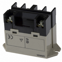
G7L-1A-BUB-J-CB-AC24
Manufacturer Part Number
G7L-1A-BUB-J-CB-AC24
Description
RELAY
Manufacturer
Omron
Series
G7Lr
Specifications of G7L-1A-BUB-J-CB-AC24
Relay Type
General Purpose
Coil Type
Standard
Contact Form
SPST-NO (1 Form A)
Contact Rating (current)
30A
Switching Voltage
250VAC - Max
Coil Current
71mA
Coil Voltage
24VAC
Turn On Voltage (max)
18 VAC
Turn Off Voltage (min)
3.6 VAC
Mounting Type
Chassis Mount
Termination Style
Screw Terminal
Circuit
SPST-NO (1 Form A)
Contact Rating @ Voltage
30A @ 220VAC
Control On Voltage (max)
18 VAC
Control Off Voltage (min)
3.6 VAC
Coil Voltage Vac Nom
24V
Contact Current Max
30A
Contact Voltage Ac Nom
220V
Coil Resistance
303ohm
Contact Configuration
SPST-NO
Lead Free Status / RoHS Status
Lead free / RoHS Compliant
Other names
G7L-1A-BUBJ-CB-AC24
G7L-1A-BUBJCBAC24
G7L-1A-BUBJCBAC24
G7L1ABUBJCBAC24
Z1053
G7L-1A-BUBJCBAC24
G7L-1A-BUBJCBAC24
G7L1ABUBJCBAC24
Z1053
Available stocks
Company
Part Number
Manufacturer
Quantity
Price
Company:

Part Number:
G7L-1A-BUB-J-CB-AC24
Manufacturer:
Omron Electronics Inc-IA Div
Quantity:
135


Precautions
HANDLING
• To preserve performance, do not drop or otherwise subject the
• The case is not designed to be removed during normal handling
• Use the Power Relay in a dry environment free from excessive
• Do not allow a voltage greater than the maximum allowable coil
• Do not use the Power Relay outside of specified voltages and
• Do not allow the ambient operating temperature to exceed the
INSTALLATION
• Although there are not specific limits on the installation site, it
• PCB Terminal-equipped Relays weigh approximately 100 g. Be
• Quick-connect terminals can be connected to Faston
• Allow suitable slack on leads when wiring, and do not subject
• G7L Relays with test buttons must be mounted facing down.
• Be careful not to touch the test button accidentally. Doing so
• Use the test button only to check the electrical conductivity. Do
CLEANING PCB TERMINALS
• PCB terminals have flux-tight construction which prevents flux
CONNECTING
• Refer to the following table when connecting a wire with a
CAT. No. J055-E2-04
Power Relay to shock.
and operation. Doing so may affect performance.
dust, SO
voltage to be applied continuously.
currents.
specified limit.
should be as dry and dust-free as possible.
sure that the PCB is strong enough to support them. We
recommend dual-side through-hole PCBs to reduce solder
cracking from heat stress.
receptacle #250 and positive-lock connectors.
the terminals to excessive force.
may turn ON the contact.
not switch the load directly by pushing the test button.
from penetrating into the Relay base housing, e.g., due to
capillary action up the terminals when Relay is soldered onto the
PCB. This type of Relay cannot be immersed for cleaning.
crimp-style terminal to the G7L.
Terminals
General Purpose Relay – G7L
Contact
Coil
2
, H
2
S, or organic gas.
M3.5
M4
terminals
Screw
9.2
8
5.8
5.5
6.5
5
Front-connecting
M3.5
M4
Socket
9.2
8
6.5
5.3
5.5
7
RATED CURRENT FLOW
• When using B-series (screw) products, the rated current from
OPERATING COIL
• As a rule, either a DC battery or a DC power supply with a
•
• When driving a transistor, check the leakage current and
DIN TRACK MOUNTING ADAPTER AND
FRONT-CONNECTING SOCKET
DIN Track Mounting
• Use a DIN-conforming 50-cm track or 1-m track (both are sold
• Cut and shorten the track to an appropriate length if the required
• The DIN Track Mounting Adapter and Front-connecting Socket
• To support the G7L mounted on a DIN Track Mounting Adapter
Screw Mounting
• Screw-mount the DIN Track Mounting Adapter or Front-
• When cutting or opening holes on the panel after the Front-
the screw terminals (M4) should be 20 A or less according to jet
standard (electrical appliance and material control law of
Japan).
maximum of 5% ripple must be used for the operating voltage
for DC Relays. Before using a rectified AC supply, confirm that
the ripple is not greater than 5%. Ripple greater than this can
lead to variations in the operating and reset voltages.
As excessive ripple can generate pulses, the insertion of a
smoothing capacitor is recommended as shown below.
connect a bleeder resistor if necessary.
separately) for mounting a number of G7L Relays.
track length is less than 50 cm.
can be mounted on the G7L with just one hand and dismounted
with ease by using a screwdriver.
or Front-connecting Socket, use the PFP-M End Plate. Put the
End Plate onto the DIN Track Mounting Adapter or Front-
connecting Socket so that the surface mark of the End Plate
faces upwards. Then tighten the screw of the End Plate securely
with a screwdriver.
connecting Socket securely after opening screw mounting holes
on them.
connecting Socket is mounted, take proper measures so that
the cutting chips will not fall onto the Relay terminals. When
cutting or opening holes on the upper part of the panel, mask
the Front-connecting Socket properly with a cover.
% of ripple =
E max.: Max. ripple
E min.:
E mean: Mean DC value
E min.E max. E mean
Min. ripple
E max. − E min.
Smoothing
capacitor
E mean
Ripple
DC fraction
x 100
Relay
479
Related parts for G7L-1A-BUB-J-CB-AC24
Image
Part Number
Description
Manufacturer
Datasheet
Request
R

Part Number:
Description:
RELAY
Manufacturer:
Omron
Datasheet:

Part Number:
Description:
RELAY
Manufacturer:
Omron
Datasheet:

Part Number:
Description:
RELAY
Manufacturer:
Omron
Datasheet:
Part Number:
Description:
RELAY
Manufacturer:
Omron
Datasheet:
Part Number:
Description:
RELAY PWR SPST 30A 24VAC
Manufacturer:
Omron
Datasheet:

Part Number:
Description:
RELAY
Manufacturer:
Omron
Datasheet:

Part Number:
Description:
RELAY; E-MECH; GEN PURP; SPST-NO; CUR-RTG 30A; CTRL-V 24DC; VOL-RTG 250AC; BRACKET MNT
Manufacturer:
Omron Automation
Datasheet:
Part Number:
Description:
G6S-2GLow Signal Relay
Manufacturer:
Omron Corporation
Datasheet:
Part Number:
Description:
Compact, Low-cost, SSR Switching 5 to 20 A
Manufacturer:
Omron Corporation
Datasheet:
Part Number:
Description:
Manufacturer:
Omron Corporation
Datasheet:
Part Number:
Description:
Manufacturer:
Omron Corporation
Datasheet: