P6B-26P Omron, P6B-26P Datasheet

PCB G6B SOCKET

P6B-26P

Manufacturer Part Number
P6B-26P
Description
PCB G6B SOCKET
Manufacturer
Omron
Series
G6Br
Type
Socketr
Datasheets

Specifications of P6B-26P

Number Of Positions
6
Mounting Type
Through Hole
Termination Style
PC Pin
Associated Relay Series
G6B-2114P, G6B-2214P
Number Of Poles
1, 2
Mounting Style
Socket
Accessory Type
Sockets
Mounting
PCB
Relay Type
Power
Standards
UL Recognized, CSA Certified
Temperature, Ambient
-25 to +70 °C
Termination
Box Clamp
Socket Mounting
PC Board
Current Rating
5A
Socket Terminals
Through Hole
Voltage Rating
250VAC
No. Of Pins
6
Length/height, External
7mm
External Width
23.2mm
External Depth
11mm
Lead Free Status / RoHS Status
Lead free / RoHS Compliant
For Use With/related Products
G6B Series, DPST
For Use With
G6B-2214P-USDC9 - RELAY PWR DPST-NO PCBG6B-2214P-US-APDC24 - RELAY PWR DPST-NO PCBG6B-2214P-FD-USDC24 - RELAY PWR DPST-NO PCBG6B-2214P-1-USDC6 - RELAY PWR DPST-NO PCBG6B-2214P-1-USDC24 - RELAY PWR DPST-NO PCBG6B-2214P-1-USDC12 - RELAY PWR DPST-NO PCBG6B-2114P-US-DC9 - RELAY PWR DPST-NO/NC PCBG6B-2114P-US-APDC12 - RELAY PWR DPST-NO/NC PCBG6B-2114P-FD-USDC5 - RELAY PWR DPST-NO/NC PCBG6B-2114P-FD-USDC12 - RELAY PWR DPST-NO/NC PCBG6B-2114P-1-US-DC9 - RELAY PWR DPST-NO/NC PCBG6B-2114P-1-USDC6 - RELAY PWR DPST-NO/NC PCBG6B-2014P-USDC6 - RELAY PWR DPST-NC PCBG6B-2014P-USDC5 - RELAY PWR DPST-NC PCBG6B-2014P-FD-USDC12 - RELAY PWR DPST-NC PCBZ2855 - RELAY PCB MINI DPST-NO 5A 48VDCG6B-2214P-1-USDC5 - RELAY PCB MINI DPST-NO 5A 5VDCG6B-2114P-US-DC48 - RELAY PCB SPST-NO/-NC 5A 48VDCZ2854 - RELAY PCB SPST-NO/-NC 5A 5VDCG6B-2114P-1USDC24 - RELAY PCB SPST-NO/-NC 5A 24VDCZ2853 - RELAY PCB SPST-NO/-NC 5A 12VDCG6B-2014P-US-DC48 - RELAY PCB MINI DPST-NC 5A 48VDCZ2852 - RELAY PCB MINI DPST-NC 5A 24VDCZ2851 - RELAY PCB MINI DPST-NC 5A 12VDCZ947 - RELAY PC MNT 5A DPST-NO 5VDCZ946 - RELAY PC MNT 5A SPST-NO/NC 5VDCZ755 - RELAY PC SPST-NO/SPST-NC 5A 6VZ758 - RELAY PC MNT DPST-NO 5A 6VDCZ759 - RELAY PC MNT DPST-NO 5A 12VDCZ760 - RELAY PC MNT DPST-NO 5A 24VDCZ757 - RELAY PC SPST-NO/SPST-NC 5A 24VZ756 - RELAY PC SPST-NO/SPST-NC 5A 12V
Lead Free Status / Rohs Status
Lead free / RoHS Compliant
Other names
P6B26P
Z994
Subminiature Relay that Switches up to 5 A
• Subminiature: 20 x 10 x 10 mm (L x W x H).
• Low power consumption: 200 mW.
• Unique moving loop armature reduces relay size, magnetic
• Fully sealed construction
• Single and Dual coil latching types also available.
• High Capacity versions available
• RoHS Compliant
Ordering Information
Model Number Legend
1. Relay Function
Non-latching
Single coil latching
Dual coil latching
High-capacity, Non-latching
Note: When ordering, add the rated coil voltage to the model number.
2. Contact Form
G6B
interference, and contact bounce time.
Power PCB Relay
G6B
None: Non-latching
U:
K:
21:
22:
20:
11:
Example: G6B-1114P-US DC12
1
Classification
Single coil latching
Dual coil latching
SPST-NO + SPST-NC
DPST-NO
DPST-NC
SPST-NO
-
2 3 4 5
-
6
SPST-NO
SPST-NO+SPST-NC
DPST-NO
DPST-NC
SPST-NO
SPST-NO
SPST-NO
-
7
DC
Contact form
3. Contact Type
4. Enclosure Ratings
5. Terminals
Rated coil voltage
8
1: Standard
7: High-capacity
4: Fully sealed
P: Straight Through-hole PCB
C: Self-clinching Through-hole PCB
G6B-1114P-US
G6B-2114P-US
G6B-2214P-US
G6B-2014P-US
G6BU-1114P-US
G6BK-1114P-US
G6B-1174P-US
Straight Through-hole PCB
6. Approved Standards
7. Mounting Method
8. Rated Coil Voltage
US:
None: Mount directly to PCB
P6B: Mount to Socket
5, 6, 12, or 24 VDC
Power PCB Relay
UL/CSA certified
G6B-1114C-US
G6B-2114C-US
G6B-2214C-US
G6B-2014C-US
G6BU-1114C-US
G6BK-1114C-US
G6B-1174C-US
Self-clinching Through-hole PCB
R
G6B
C+
149

Related parts for P6B-26P

P6B-26P Summary of contents

Page 1

... High-capacity 7. Mounting Method 4: Fully sealed 8. Rated Coil Voltage P: Straight Through-hole PCB C: Self-clinching Through-hole PCB C+ R Self-clinching Through-hole PCB G6B-1114C-US G6B-2114C-US G6B-2214C-US G6B-2014C-US G6BU-1114C-US G6BK-1114C-US G6B-1174C-US US: UL/CSA certified None: Mount directly to PCB P6B: Mount to Socket VDC G6B 149 Power PCB Relay ...

Page 2

... Back Connecting Sockets Applicable Relay Back Connecting Socket (See note 1.) G6B(U)-1114P-US-P6B P6B-04P G6BK-1114P-US-P6B P6B-06P G6B-2@@4P-US-P6B P6B-26P G6B-1174P-US-P6B P6B-04P Note: 1. Not applicable to the self-clinching type. 2. Use the G6B-@@@@P-US-P6B if mounting relays in a P6B Socket. Removal Tool P6B-Y1 Hold-down Clips P6B-C2 Specifications ■ ...

Page 3

Non-latching, Double Pole Rated Rated Coil voltage current resistance (VDC) (mA) (Ω 83. 120 12 25 480 24 12.50 1,920 Single Coil Latching Rated Rated Coil voltage current resistance (VDC) (mA) (Ω) Armature OFF Armature ON ...

Page 4

Approved Standards UL Recognized (File No. E41643) / CSA Certified (File No. LR31928) Model G6B-1114P-US SPST-NO G6B-1114C-US G6BU-1114P-US G6BU-1114C-US G6BK-1114C-US G6BK-1114C-US G6B-1174P-US G6B-1174C-US G6B-2114P-US SPST-NO + SPST-NC G6B-2114C-US DPST-NO G6B-2214P-US DPST-NC G6B-2214C-US G6B-2014P-US G6B-2014C-US Engineering Data G6B-1114P-US Maximum Switching ...

Page 5

Dimensions Note: 1. All units are in millimeters unless otherwise indicated. 2. Orientation marks are indicated as follows: ■ Single Pole G6B-1114P-US G6BU-1114P-US 10 max. * (9.8) 0.3 3.5 0.85 0.9 20 max. (19.9) * 0.5 *Average value G6B-1114C-US G6BU-1114C-US ...

Page 6

Double Pole G6B-2114P-US 20 max. (19.9)* G6B-2214P-US G6B-2014P-US 11 max. (10.9)* 11 max. (10.9)* 3.5 10.16 G6B-2114C-US G6B-2214C-US 20 max. (19.9)* G6B-2014C-US 11 max. (10.9)* 11 max. (10.9)* 3.5 10.16 G6B 154 Power PCB Relay Terminal Arrangement/Internal Connections (Bottom ...

Page 7

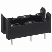
... Back Connecting Socket P6B-04P 10 max. (9.9)* 10.1 max. (10)* P6B-06P 23.2 max. (23)* 10 max. (9.9)* 10.1 max. (10)* 7 3.5 7.62 P6B-26P 23.2 max. (23)* 11 max. (10.8)* 10.1 max. (10)* Removal Tool P6B-Y1 23.2 max. (23)* *Average value Mounting Holes (Bottom View) 2.54 7.62 7. ...

Page 8

MEMO G6B 156 Power PCB Relay ...

Page 9

... Seller within 30 days of receipt of shipment. III. PRECAUTIONS 1. Suitability THE BUYER’S SOLE RESPOINSIBILITY TO ENSURE THAT ANY OMRON PRODUCT IS FIT AND SUFFICIENT FOR USE IN A MOTORIZED VEHICLE APPLICATION. BUYER SHALL BE SOLELY RESPONSIBLE FOR DETERMINING APPROPRIATENESS OF THE PARTICULAR PRODUCT WITH RESPECT TO THE BUYER’ ...

Page 10

... THE OMRON PRODUCT IS PROPERLY RATED AND INSTALLED FOR THE INTENDED USE WITHIN THE OVERALL EQUIPMENT OR SYSTEM. Complete “Terms and Conditions of Sale” for product purchase and use are on Omron’s website at http://www.components.omron.com – under the “About Us” tab, in the Legal Matters section. ...

Related keywords