XS2C-D421 Omron, XS2C-D421 Datasheet
XS2C-D421
Specifications of XS2C-D421


Related parts for XS2C-D421


XS2C-D421 Summary of contents
Page 1
... Materials (UL94V-0) (UL94V-0) (UL94V-0) Finish For DC: light gray; for AC: dark gray Polyester PBT resin --- elastomer (UL94V-0) PBT resin --- --- (UL94V-0) PA resin --- --- (UL94V-0) PBT resin --- --- (UL94V-0) LCP resin --- --- (UL94V-0) --- --- Rubber --- --- Steel DC type AC type Female (socket) Male (plug) Female (socket) contacts contacts contacts XS2C ...
Page 2
... XS2W Sockets and Plugs on Cable Ends XS2F Sockets on One Cable End 1. Connectors attached to Cable XS2H Plugs on One Cable End XS2G Plug Assemblies XS2C Socket Assemblies 2. Connector Assemblies (Crimp- ing, Soldering, or Screw-on) XY2F Crimp Tool (for Crimping Connectors) Used to enable using connec- tors for sensor cables and relay cables ...
Page 3
XS2W Sockets and Plugs on Cable Ends Model Number Legend Use this model number legend to identify products from their model number. When ordering, use a model number from the table in Ordering Information. XS2W-D@2@-@@1 ...
Page 4
... Standard ca- Straight/Straight ble L-shaped/L-shaped Straight/L-shaped 4 L-shaped/Straight Vibration- Straight/Straight proof robot cable Note: Ask your OMRON representative about other cable lengths, and about 5-core cables. 14.9 dia. 44.7 14.9 dia. 32.3 25.3 Wiring Diagram for 4 Cores 14.9 dia. Contact No. 32.3 25.3 Wiring Diagram for 5 Cores Contact No ...
Page 5
... Connectors on One End/Both Ends 0: One end 9. Cable Specifications A: Standard cable R: Vibration-proof robot cable F: Fire- retardant E: Heat-resistant cable up to 105°C R type 4-core cable type is a 4-core cable. Designations for DC Polarity (For Limit Switches and Sensors) 6. Cable Length Connections Pin No --- 8. Connectors on One End/Both Ends 0: One end 9 ...
Page 6
XS2F Sockets on One Cable End ● Connectors with Standard Cable XS2F-@42@-@@0-A ● Connectors with Vibration-proof Robot Cable XS2F-@42@-@@0-R ● Non-polar DC Connectors with Standard Cable XS2F-@42@-@@0 Dimensions Straight Connectors M12 45° 5 dia. 5 dia. DC L-shaped Connectors 28.3 ...
Page 7
... Straight 2 (E2E models with conventional 2 L-shaped connector pin) 2 Straight Heat-resistant 4 cable * L-shaped Note: Ask your OMRON representative about other cable lengths. *The heat-resistant fixture material is SUS316L stainless steel without surface treatment. DC No. of cable Cable cores length (m) Model XS2F-D421-CA0-A 1 XS2F-D421-CC0-A XS2F-D421-C80-A XS2F-D421-DA0-A 2 ...
Page 8
... Connectors for DC XS2F-D521-@G0-A Dimensions Straight Connectors M12 5 dia. Ordering Information No. of cable Cable core Cable length cores cross-sectional 2 area ( 0.3 mm Note: Ask your OMRON representative about other cable lengths. 18 45° 6 dia. 14.9 dia Wiring Diagram Contact No. Cable lead colors Brown 1 White 2 3 ...
Page 9
XS2H Plugs on One Cable End Model Number Legend XS2H-@@21-@@0 Type H: Connector connected to cable, plug on one cable end 2. AC/DC A: For AC D: For DC 3. Connector ...
Page 10
XS2H Plugs on One Cable End ● Connectors on Standard Cable XS2H-@421-@@0-A Dimensions Straight Connectors 5 dia. DC Wiring Diagram Contact No. Cable lead colors 1 Brown 2 3 Blue 4 (DC) Contact No. Cable lead colors 1 2 Brown ...
Page 11
XS2@ Sensor I/O Connectors on Cables (8-pole) Ordering Information Connector type Panel-mounting socket Panel-mounting plug Plug on one cable end Socket on one cable end Plug and socket on cable ends Pin Numbers and Cable Lead Colors 1 XS2F/XS2H/XS2W cable ...
Page 12
Dimensions XS2H Plug on One Cable End (M12) XS2F Socket on One Cable End (M12) XS2W Plug and Socket on Cable Ends (M12) XS2P-D821-2 Panel-mounting Socket (M12) with Solder Cup Pins and Rear Lock 1.5 Seal rubber 20 dia. 14 ...
Page 13
XS2G Crimping/Soldering Plug Assemblies Dimensions XS2G-@4C@ (Crimping Model) XS2G-@42@ (Soldering Model) Straight Connectors XS2G-D42@ (Soldering Model) L-shaped Connectors Ordering Information Suitable cable dia. Cable connection (mm) direction Straight 6-mm-dia. model ( dia.) L-shaped Straight 4-mm-dia. model (4 ...
Page 14
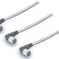
... M12 M12 14.9 dia 45° 45° 31.8 5 dia. 5 dia. M12 M12 14.9 dia Connection method Model Crimping XS2C-D4C1 Soldering XS2C-D421 Crimping XS2C-D4C2 Soldering XS2C-D422 Crimping XS2C-D4C3 Soldering XS2C-D423 Crimping XS2C-D4C4 Soldering XS2C-D424 Crimping XS2C-D4C5 Soldering XS2C-D425 Crimping XS2C-D4C6 Soldering XS2C-D426 Note: A special tool must be used for crimping. For details, refer to page 23. ...
Page 15
XS2G Screw-on Plug Assemblies Dimensions XS2G-D5S7 (5-pole, Straight, Applicable Cable Outer Diameter: 8 mm) XS2G-D5S9 (5-pole, Straight, Applicable Cable Outer Diameter: 7 mm) XS2G-D4S7 (4-pole, Straight, Applicable Cable Outer Diameter: 8 mm) XS2G-D4S9 (4-pole, Straight, Applicable Cable Outer Diameter: 7 ...
Page 16
... XS2C-D5S1 (5-pole, Straight, Applicable Cable Outer Diameter: 6 mm) XS2C-D4S@ (4-pole, Straight, Applicable Cable Outer Diameter mm) M12 × 1 XS2C-D5S2 (5-pole, L-shaped, Applicable Cable Outer Diameter: 6 mm) XS2C-D4S@ (4-pole, L-shaped, Applicable Cable Outer Diameter mm) Ordering Information No. of poles Suitable cable dia. (mm) 8-mm-dia. model ( dia.) 5 7-mm-dia ...
Page 17
XS2P Panel-mounting Sockets for Terminal Boxes Dimensions XS2P-@421-2 (with Solder Cup Pins) Rear Lock Model M12 DC XS2P-@422-1 (with DIP Pins) XS2P-@422-2 (with Solder Cup Pins) Front Lock Model M12 7 DC Panel Cutout +0 min. Note: ...
Page 18
XS2R Y-Joint Plug/Socket Connectors Dimensions XS2R-D426-@11-F Connectors on Both Cable Ends (Y-Joint Plug/Socket) 45.5 15.0 4.6 dia. CN2 35.0 18 CN1 Blue marking XS2R-D426-@10-F Connectors on One Cable End (Y-Joint Plug/Socket) 15.0 ...
Page 19
XS2R T-Joint Plug/Socket Connectors Dimensions XS2R-D422-1 XS2R-D422-5 Aggregate Models XS2R-D423-1 Bifurcated Model XS2R-D424-1 Daisy-chain Model Ordering Information Type Model XS2R-D422-1 Aggregate model XS2R-D422-5 Bifurcated model XS2R-D423-1 Daisy-chain model XS2R-D424-1 50.6 24.6 M12 A B 14.6 dia M12 50.6 ...
Page 20
... A Sensor1 Sensor2 Safety Precautions Precautions for Correct Use Do not use this product under ambient conditions that exceed the ratings. Sensor XS2G/XS2H B C XS2W/XS2F/XS2C XS2W/XS2F/XS2C B C XS2G/XS2H Sensor Sensor2 Before using the XS2R for Sensors, make sure that the wiring of the Sensors and the internal connections of the XS2R are correct. • ...
Page 21
XS2M Sensor-embedded Plugs Dimensions XS2M-D421 (DC) XS2M-A421 (AC) (Embedded Plug with Screw Threads) 45° 5 dia. DC XS2M-D422 (DC) XS2M-A422 (AC) (Embedded Plug without Screw Threads) 5 dia. 45° DC XS2M Panel-mounting Plugs Dimensions XS2M-D423 (For DC) XS2M-A423 (For AC) ...
Page 22
... Model XS2G/XS2H/XS2M/XS2R/XS2W/XS5H/ XS5M/XS5W XS2C/XS2R/XS2F/XS2P/XS2W/XW3B/ XS5F/XS5W/XS5R/XS5P/XW3D M12 male screw M12 female screw (thread bracket) XS2Z-14 Pin block (female pins) Material Model XS2G/XS2H/XS2M/XS2R XS2C/XS2R/XS2F/XS2P/ XW3A/XW3B M12 female screw (thread bracket) Pin block (female contact) Applicable connector XS2F/XS2H/XS2W AC Minimum order Model XS2M-A421 XS2M-A422 XS2M-A423 ...
Page 23
... Pin-block Extraction Tool XY2F-0001 Use this tool to extract a Pin Block from the covers in order to make wiring changes or corrections after the cover has been mounted to the pin block for Connector Assemblies (XS2C/ XS2G, soldering/crimping). Extraction Procedure (1) Disconnecting Components • Disconnect all components on the cap side from the cover. ...
Page 24
... Assembly Procedure for XS2C/XS2G Connector Assemblies (1) Connector and Cable External Diameters • Connectors for 6-, 4-, and 3-mm-diameter Cables (i.e., Cables that are and diameter respectively) are available. When assembling a Connector used with a cable, make sure that the external diameter of the Connector is suited to that of the cable. ...
Page 25
... Insertion Pin Block Pin Clamp XS2C use XS2G use Key • Tentatively insert the pins to the pin block holes so that the key on the pin block will coincide with the key groove on the pin clamp. Then insert the cable along with the pin clamp. ...
Page 26
Pin Block (Screw-mounting Connectors) Cover Triangle mark Cover lock Pin block • Align the triangular marks on the pin block and cover and insert the pin block into the cover. • Press them together firmly (0.39 to 0.49 N·m) until ...
Page 27
... Cancellation; Etc. Orders are not subject to rescheduling or cancellation unless Buyer indemnifies Omron against all related costs or expenses. 10. Force Majeure. Omron shall not be liable for any delay or failure in delivery resulting from causes beyond its control, including earthquakes, fires, floods, strikes or other labor disputes, shortage of labor or materials, accidents to machinery, acts of sabotage, riots, delay in or lack of transportation or the requirements of any government authority ...
Page 28
... OMRON ELECTRONICS LLC • THE AMERICAS HEADQUARTERS Schaumburg, IL USA • 847.843.7900 • 800.556.6766 • www.omron247.com OMRON CANADA, INC. • HEAD OFFICE Toronto, ON, Canada • 416.286.6465 • 866.986.6766 • www.omron.ca OMRON ELETRÔNICA DO BRASIL LTDA • HEAD OFFICE São Paulo, SP, Brasil • 55.11.2101.6300 • www.omron.com.br OMRON ELECTRONICS MEXICO • ...