MUR140RLG ON Semiconductor, MUR140RLG Datasheet - Page 4
MUR140RLG
Manufacturer Part Number
MUR140RLG
Description
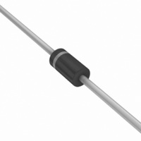
DIODE ULTRA FAST 1A 400V DO-41
Manufacturer
ON Semiconductor
Series
SWITCHMODE™r
Datasheet
1.MUR160RLG.pdf
(7 pages)
Specifications of MUR140RLG
Voltage - Forward (vf) (max) @ If
1.25V @ 1A
Voltage - Dc Reverse (vr) (max)
400V
Current - Average Rectified (io)
1A
Current - Reverse Leakage @ Vr
5µA @ 400V
Diode Type
Standard
Speed
Fast Recovery =< 500ns, > 200mA (Io)
Reverse Recovery Time (trr)
75ns
Mounting Type
Through Hole
Package / Case
DO-204AL, DO-41, Axial
Product
Ultra Fast Recovery Rectifier
Configuration
Single
Reverse Voltage
400 V
Forward Voltage Drop
1.25 V
Recovery Time
75 ns
Forward Continuous Current
1 A @ Ta=120C
Max Surge Current
35 A
Reverse Current Ir
5 uA
Mounting Style
Through Hole
Maximum Operating Temperature
+ 175 C
Minimum Operating Temperature
- 65 C
Rectifier Type
Switching Diode
Peak Rep Rev Volt
400V
Avg. Forward Curr (max)
1A
Rev Curr
5uA
Peak Non-repetitive Surge Current (max)
35A
Forward Voltage
1.25V
Operating Temp Range
-65C to 175C
Package Type
DO-41
Rev Recov Time
75ns
Operating Temperature Classification
Military
Mounting
Through Hole
Pin Count
2
Lead Free Status / RoHS Status
Lead free / RoHS Compliant
Capacitance @ Vr, F
-
Lead Free Status / Rohs Status
Lead free / RoHS Compliant
Other names
MUR140RLGOS
MUR140RLGOS
MUR140RLGOSTR
MUR140RLGOS
MUR140RLGOSTR
Available stocks
Company
Part Number
Manufacturer
Quantity
Price
Company:

Part Number:
MUR140RLG
Manufacturer:
ON
Quantity:
100 000
Part Number:
MUR140RLG
Manufacturer:
ON/安森美
Quantity:
20 000


0.07
0.05
0.03
0.02
0.01
5.0
4.0
3.0
2.0
1.0
7.0
5.0
3.0
2.0
1.0
0.7
0.5
0.3
0.2
0.1
10
0
0
0.3
T
0.5
J
= 175°C
I
F(AV)
Figure 6. Typical Forward Voltage
(CAPACITIVE LOAD)
T
0.5
J
0.7
= 175°C
v
Figure 9. Power Dissipation
, AVERAGE FORWARD CURRENT (AMPS)
F,
INSTANTANEOUS VOLTAGE (VOLTS)
I
I
PK
AV
0.9
+ 20
1.0
1.1
25°C
1.3
100°C
1.5
10
1.5
1.7
SQUARE WAVE
MUR130, MUR140, MUR160
2.0
1.9
5.0
http://onsemi.com
MUR120 Series
2.1
dc
2.5
2.3
4
0.004
0.04
0.01
400
100
4.0
1.0
0.4
0.1
5.0
4.0
3.0
2.0
1.0
7.0
5.0
3.0
2.0
40
10
20
10
0
0
0
0
* The curves shown are typical for the highest voltage device in the
voltage grouping. Typical reverse current for lower voltage selections
can be estimated from these same curves if V
rated V
R
100
.
Figure 7. Typical Reverse Current*
(Mounting Method #3 Per Note 2)
50
10
Figure 10. Typical Capacitance
Figure 8. Current Derating
SQUARE WAVE
T
V
200
A
R
V
, AMBIENT TEMPERATURE (°C)
, REVERSE VOLTAGE (VOLTS)
R
, REVERSE VOLTAGE (VOLTS)
100
20
300
T
dc
J
100°C
= 175°C
25°C
400
150
30
R
R
qJA
RATED V
is sufficiently below
500
= 50°C/W
200
40
T
J
R
= 25°C
600
250
700
50
Related parts for MUR140RLG
Image
Part Number
Description
Manufacturer
Datasheet
Request
R

Part Number:
Description:
DIODE ULTRA FAST 1A 400V DO-41
Manufacturer:
ON Semiconductor
Datasheet:

Part Number:
Description:
ON Semiconductor [VOLTAGE REGULATOR]
Manufacturer:
ON Semiconductor
Datasheet:
Part Number:
Description:
357-036-542-201 CARDEDGE 36POS DL .156 BLK LOPRO
Manufacturer:
ON Semiconductor
Datasheet:
Part Number:
Description:
357-036-542-201 CARDEDGE 36POS DL .156 BLK LOPRO
Manufacturer:
ON Semiconductor
Datasheet:
Part Number:
Description:
357-036-542-201 CARDEDGE 36POS DL .156 BLK LOPRO
Manufacturer:
ON Semiconductor
Datasheet:
Part Number:
Description:
357-036-542-201 CARDEDGE 36POS DL .156 BLK LOPRO
Manufacturer:
ON Semiconductor
Datasheet:
Part Number:
Description:
357-036-542-201 CARDEDGE 36POS DL .156 BLK LOPRO
Manufacturer:
ON Semiconductor
Datasheet:
Part Number:
Description:
357-036-542-201 CARDEDGE 36POS DL .156 BLK LOPRO
Manufacturer:
ON Semiconductor
Datasheet:
Part Number:
Description:
357-036-542-201 CARDEDGE 36POS DL .156 BLK LOPRO
Manufacturer:
ON Semiconductor
Datasheet:
Part Number:
Description:
357-036-542-201 CARDEDGE 36POS DL .156 BLK LOPRO
Manufacturer:
ON Semiconductor
Datasheet:
Part Number:
Description:
357-036-542-201 CARDEDGE 36POS DL .156 BLK LOPRO
Manufacturer:
ON Semiconductor
Datasheet:
Part Number:
Description:
357-036-542-201 CARDEDGE 36POS DL .156 BLK LOPRO
Manufacturer:
ON Semiconductor
Datasheet:
Part Number:
Description:
Manufacturer:
ON Semiconductor
Datasheet:
Part Number:
Description:
Manufacturer:
ON Semiconductor
Datasheet: