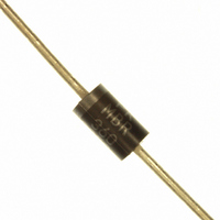
MBR360RLG ON Semiconductor, MBR360RLG Datasheet - Page 3

MBR360RLG
Manufacturer Part Number
MBR360RLG
Description
DIODE SCHOTTKY 60V 3A DO201AD
Manufacturer
ON Semiconductor
Specifications of MBR360RLG
Voltage - Forward (vf) (max) @ If
740mV @ 3A
Voltage - Dc Reverse (vr) (max)
60V
Current - Average Rectified (io)
3A
Current - Reverse Leakage @ Vr
600µA @ 60V
Diode Type
Schottky
Speed
Fast Recovery =< 500ns, > 200mA (Io)
Mounting Type
Through Hole
Package / Case
DO-201AD, Axial
Product
Schottky Diodes
Peak Reverse Voltage
60 V
Forward Continuous Current
3 A @ Ta=65C
Max Surge Current
80 A
Configuration
Single
Forward Voltage Drop
1.08 V @ 9.4 A
Maximum Reverse Leakage Current
600 uA
Operating Temperature Range
- 65 C to + 150 C
Mounting Style
Through Hole
Current, Forward
3 A
Current, Reverse
20 mA
Current, Surge
80 A
Package Type
DO-201AD
Primary Type
Schottky Barrier
Temperature, Junction, Maximum
+150 °C
Temperature, Operating
-65 to +150 °C
Voltage, Forward
1.08 V
Voltage, Reverse
60 V
Lead Free Status / RoHS Status
Lead free / RoHS Compliant
Reverse Recovery Time (trr)
-
Capacitance @ Vr, F
-
Lead Free Status / Rohs Status
Lead free / RoHS Compliant
Other names
MBR360RLGOSTR
Available stocks
Company
Part Number
Manufacturer
Quantity
Price
Company:
Part Number:
MBR360RLG
Manufacturer:
ON Semiconductor
Quantity:
1 000
Part Number:
MBR360RLG
Manufacturer:
ON/安森美
Quantity:
20 000
É É É É É É É É É É
É É É É É É É É É É
†For information on tape and reel specifications, including part orientation and tape sizes, please refer to our Tape and Reel Packaging
ORDERING INFORMATION
Specifications Brochure, BRD8011/D.
MBR350RL
MBR350RLG
MBR360
MBR360G
MBR360RL
MBR360RLG
5.0
4.0
3.0
2.0
1.0
0
P.C. Board where available
Mounting Method 1
0
typical guideline values for preliminary engineering, or in case the tie point temperature cannot be measured.
copper surface is small.
Data shown for thermal resistance, junction−to−ambient (R
L
I
F (AV)
1.0
Figure 4. Power Dissipation
, AVERAGE FORWARD CURRENT (AMPS)
T
Device
J
= 150°C
L
2.0
SQUARE
3.0
WAVE
É É É É É É É É É É É
Mounting
Method
TYPICAL VALUES FOR R
1
2
3
dc
NOTE 4 — MOUNTING DATA
Vector Push−In Terminals T−28
4.0
MBR350, MBR360
Mounting Method 2
http://onsemi.com
L
1/8
58
50
Lead Length, L (in)
5.0
1/4
51
59
3
Axial Lead
Axial Lead
Axial Lead
Axial Lead
Axial Lead
Axial Lead
28
(Pb−Free)
(Pb−Free)
(Pb−Free)
Package
1/2
53
61
qJA
300
200
100
70
50
40
30
IN STILL AIR
qJA
0
L
3/4
55
63
) for the mountings shown is to be used as
°C/W
°C/W
°C/W
R
qJA
10
Figure 5. Typical Capacitance
V
R
, REVERSE VOLTAGE (VOLTS)
É É
É É É É
É É
É É É É
É É
P.C. Board with 2−1/2 in X 2−1/2 in
20
1500 Units / Tape & Reel
1500 Units / Tape & Reel
1500 Units / Tape & Reel
1500 Units / Tape & Reel
Mounting Method 3
Board Ground Plane
500 Units / Bag
500 Units / Bag
L = 1/2’’
copper surface.
Shipping
30
T
J
= 25°C
†
40
50


