MBR1645-E3/45 Vishay, MBR1645-E3/45 Datasheet - Page 4
MBR1645-E3/45
Manufacturer Part Number
MBR1645-E3/45
Description
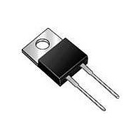
DIODE SCHOTT 16A 45V SGL TO220-3
Manufacturer
Vishay
Specifications of MBR1645-E3/45
Diode Type
Schottky
Voltage - Forward (vf) (max) @ If
630mV @ 16A
Voltage - Dc Reverse (vr) (max)
45V
Current - Average Rectified (io)
16A
Current - Reverse Leakage @ Vr
200µA @ 45V
Speed
Fast Recovery =< 500ns, > 200mA (Io)
Mounting Type
Through Hole
Package / Case
TO-220-3 (Straight Leads)
Product
Schottky Diodes
Peak Reverse Voltage
45 V
Forward Continuous Current
16 A
Max Surge Current
150 A
Configuration
Single
Forward Voltage Drop
0.63 V
Maximum Reverse Leakage Current
200 uA
Operating Temperature Range
- 65 C to + 150 C
Mounting Style
Through Hole
Repetitive Reverse Voltage Vrrm Max
45V
Forward Current If(av)
16A
Forward Voltage Vf Max
570mV
Forward Surge Current Ifsm Max
1.8kA
Rectifier Type
Schottky Diode
Peak Rep Rev Volt
45V
Avg. Forward Curr (max)
16A
Rev Curr
200uA
Peak Non-repetitive Surge Current (max)
150A
Forward Voltage
0.63V
Operating Temp Range
-65C to 150C
Package Type
TO-220AC
Operating Temperature Classification
Military
Mounting
Through Hole
Pin Count
2 +Tab
Lead Free Status / RoHS Status
Lead free / RoHS Compliant
Reverse Recovery Time (trr)
-
Capacitance @ Vr, F
-
Lead Free Status / Rohs Status
Lead free / RoHS Compliant


MBR16.. Series
Vishay High Power Products
Note
(1)
www.vishay.com
4
Formula used: T
Pd = Forward power loss = I
Pd
REV
= Inverse power loss = V
155
150
145
140
135
130
125
120
Fig. 5 - Maximum Allowable Case Temperature vs.
0
Square wave (D = 0.50)
Rated V
See note (1)
C
I
F(AV)
= T
J
5
R
- Average Forward Current (A)
- (Pd + Pd
Average Forward Current
applied
F(AV)
10
R1
Current
monitor
REV
x V
x I
FM
) x R
R
D.U.T.
(1 - D); I
15
For technical questions, contact: diodes-tech@vishay.com
at (I
thJC
10 000
Fig. 7 - Maximum Non-Repetitive Surge Current (Per Leg)
F(AV)
DC
1000
;
100
R
20
/D) (see fig. 6);
at V
Fig. 8 - Unclamped Inductive Test Circuit
10
Schottky Rectifier, 16 A
R1
t
p
- Square Wave Pulse Duration (µs)
= Rated V
25
R
IRFP460
g
= 25 Ω
L
100
R
At any rated load condition
and with rated V
following surge
applied
Freewheel
40HFL40S02
1000
diode
High-speed
RRM
switch
applied
15
10
5
0
0
Fig. 6 - Forward Power Loss Characteristics
10 000
+
I
F(AV)
V
d
5
= 25 V
- Average Forward Current (A)
DC
10
Document Number: 93441
15
Revision: 22-Aug-08
D = 0.75
D = 0.50
D = 0.33
D = 0.25
D = 0.20
RMS limit
20
25
Related parts for MBR1645-E3/45
Image
Part Number
Description
Manufacturer
Datasheet
Request
R

Part Number:
Description:
DIODE SCHOTTKY 45V 16A TO-220AC
Manufacturer:
Vishay
Datasheet:
Part Number:
Description:
DIODE SCHOTTKY 16A 45V TO-220AC
Manufacturer:
Vishay
Datasheet:

Part Number:
Description:
357-036-542-201 CARDEDGE 36POS DL .156 BLK LOPRO
Manufacturer:
Vishay
Datasheet:
Part Number:
Description:
357-036-542-201 CARDEDGE 36POS DL .156 BLK LOPRO
Manufacturer:
Vishay
Datasheet:
Part Number:
Description:
357-036-542-201 CARDEDGE 36POS DL .156 BLK LOPRO
Manufacturer:
Vishay
Datasheet:
Part Number:
Description:
357-036-542-201 CARDEDGE 36POS DL .156 BLK LOPRO
Manufacturer:
Vishay
Datasheet:
Part Number:
Description:
357-036-542-201 CARDEDGE 36POS DL .156 BLK LOPRO
Manufacturer:
Vishay
Datasheet:
Part Number:
Description:
357-036-542-201 CARDEDGE 36POS DL .156 BLK LOPRO
Manufacturer:
Vishay
Datasheet:
Part Number:
Description:
357-036-542-201 CARDEDGE 36POS DL .156 BLK LOPRO
Manufacturer:
Vishay
Datasheet:
Part Number:
Description:
357-036-542-201 CARDEDGE 36POS DL .156 BLK LOPRO
Manufacturer:
Vishay
Datasheet:
Part Number:
Description:
357-036-542-201 CARDEDGE 36POS DL .156 BLK LOPRO
Manufacturer:
Vishay
Datasheet:
Part Number:
Description:
357-036-542-201 CARDEDGE 36POS DL .156 BLK LOPRO
Manufacturer:
Vishay
Datasheet:
Part Number:
Description:
357-036-542-201 CARDEDGE 36POS DL .156 BLK LOPRO
Manufacturer:
Vishay
Datasheet:
Part Number:
Description:
357-036-542-201 CARDEDGE 36POS DL .156 BLK LOPRO
Manufacturer:
Vishay
Datasheet:
Part Number:
Description:
357-036-542-201 CARDEDGE 36POS DL .156 BLK LOPRO
Manufacturer:
Vishay
Datasheet: