A16Z-3004 Omron, A16Z-3004 Datasheet - Page 9
A16Z-3004
Manufacturer Part Number
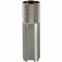
A16Z-3004
Description
SCREEN FITTING
Manufacturer
Omron
Type
Pushbuttonr
Series
A16, M 16r
Specifications of A16Z-3004
Illumination
Not Illuminated
Height
60 mm
Lead Free Status / RoHS Status
Lead free / RoHS Compliant
For Use With
Z1398 - SWTCH KNOB RND 3POS DPDT ILL YLWZ1397 - SWTCH KNOB RND 3POS DPDT ILL REDZ1396 - SWTCH KNOB RND 3POS DPDT ILL GRNZ1395 - SWTCH KNOB RND 2POS SPDT ILL YLWZ1394 - SWTCH KNOB RND 2POS SPDT ILL REDZ1393 - SWTCH KNOB RND 2POS SPDT ILL GRNZ1392 - SWTCH KNOB RND 2POS SPDT ILL YLWZ1391 - SWTCH KNOB RND 2POS SPDT ILL REDZ1390 - SWTCH KNOB RND 2POS SPDT ILL GRNZ1389 - SWITCH KNOB RND 3-POS DPDTZ1388 - SWITCH KNOB RND 2-POS SPDTZ1387 - SWITCH KNOB RND 2-POS SPDTZ1386 - SWITCH KNB RECT 3POS DPDT ILLZ1385 - SWITCH KNB RECT 3POS DPDT ILLZ1384 - SWITCH KNB RECT 3POS DPDT ILLZ1383 - SWITCH KNB RECT 2POS SPDT ILLZ1382 - SWITCH KNB RECT 2POS SPDT ILLZ1381 - SWITCH KNB RECT 2POS SPDT ILLZ1380 - SWITCH KNB RECT 2POS SPDT ILLZ1379 - SWITCH KNB RECT 2POS SPDT ILLZ1378 - SWITCH KNB RECT 2POS SPDT ILLZ1377 - SWITCH KNOB RECT 3-POS DPDTZ1376 - SWITCH KNOB RECT 2-POS SPDTZ1375 - SWITCH KNOB RECT 2-POS SPDTZ1374 - SWITCH KNOB SQ 3-POS DPDT ILLZ1373 - SWITCH KNOB SQ 3-POS DPDT ILLZ1372 - SWITCH KNOB SQ 3-POS DPDT ILLZ1371 - SWITCH KNOB SQ 2-POS SPDT ILLZ1370 - SWITCH KNOB SQ 2-POS SPDT ILLZ1369 - SWITCH KNOB SQ 2-POS SPDT ILLZ1368 - SWITCH KNOB SQ 2-POS SPDT ILLZ1367 - SWITCH KNOB SQ 2-POS SPDT ILLZ1366 - SWITCH KNOB SQ 2-POS SPDT ILLZ1365 - SWITCH KNOB SQ 3-POS DPDTZ1364 - SWITCH KNOB SQ 2-POS SPDTZ1363 - SWITCH KNOB SQ 2-POS SPDTZ1328 - SWITCH PB ROUND MOM SPDT YELLOWZ1327 - SWITCH PB ROUND MOM SPDT WHITEZ1326 - SWITCH PB ROUND MOM SPDT REDZ1325 - SWITCH PB ROUND MOM SPDT GREENZ1324 - SWITCH PB ROUND MOM SPDT BLACKZ1323 - SWITCH PB ROUND MOM SPDT BLUEZ1322 - SWITCH PB RECT MOM DPDT YELLOWZ1321 - SWITCH PB RECT MOM DPDT WHITEZ1320 - SWITCH PB RECT MOM DPDT REDZ1319 - SWITCH PB RECT MOM DPDT GREENZ1318 - SWITCH PB RECT MOM DPDT BLACKZ1317 - SWITCH PB SQUARE MOM DPDT YELLOWZ1316 - SWITCH PB SQUARE MOM DPDT WHITEZ1315 - SWITCH PB SQUARE MOM DPDT REDZ1314 - SWITCH PB SQUARE MOM DPDT GREENZ1313 - SWITCH PB SQUARE MOM DPDT BLACKZ1312 - SWITCH PB SQUARE MOM DPDT BLUEZ1311 - SWITCH PB RND MOM DPDT ILLUM YLWZ1310 - SWITCH PB RND MOM DPDT ILLUM WHTZ1309 - SWITCH PB RND MOM DPDT ILLUM REDZ1308 - SWITCH PB RND MOM DPDT ILLUM GRNZ1307 - SWITCH PB RECT MOM DPDT ILLUMZ1306 - SWITCH PB RECT MOM DPDT ILLUMZ1305 - SWITCH PB RECT MOM DPDT ILLUMZ1304 - SWITCH PB RECT MOM DPDT ILLUMZ1303 - SWITCH PB SQ MOM DPDT ILLUM YLLWZ1302 - SWITCH PB SQ MOM DPDT ILLUM WHTZ1301 - SWITCH PB SQ MOM DPDT ILLUM REDZ1300 - SWITCH PB SQ MOM DPDT ILLUM GRN
Lead Free Status / Rohs Status
Lead free / RoHS Compliant
Other names
A16Z3004
A3B-3004
SW183
SW183
Z1436
A3B-3004
SW183
SW183
Z1436


Safety Precautions
Be sure to read the precautions for all pushbutton switches in the Pushbutton Switches Group Catalog (Cat. No. X032).
If the Operation Unit is separated from the Switch Unit, the
equipment will not stop, creating a hazardous condition.
Always confirm that safety functions are operating before
starting operation.
Mounting
Wiring
Operating Environment
Using the Microload
• Always make sure that the power is turned OFF before mounting,
• The tightening torque is 0.29 to 0.49 N·m.
• Be sure to use electrical wires that are a size appropriate for the
• Use non-corrosive resin fluid as the flux.
• Make sure that the electric cord is wired so that it does not touch
• After wiring the Switch, maintain an appropriate clearance and
• The IP65 model is designed with a degree of protection so that it
• The Switch is intended for indoor use only. Using the Switch
• Insert a contact protection circuit, if necessary, to prevent the
• The A165E-@U (one-piece construction) allows both a standard
• The minimum applicable load is the N-level reference value. This
• The equation, λ
removing, or wiring the Switch, or performing maintenance.
Electrical shock or fire may result if the power is not turned OFF.
applied voltage and carry current. Perform soldering according to
the conditions given below. If the soldering is not properly
performed, abnormal heating may result, possibly resulting in fire.
1. Hand soldering: 30 W, within 5 s
2. Dip soldering: 240°C, within 3 s
Wait for one minute after soldering before exerting any external
force on the solder.
the Unit. If the electric cord will touch the Unit, then electric wires
with a heat resistance of 100°C min. must be used.
creepage distance.
will not sustain damage if it is subjected to water from any direction
to the front of the panel.
outdoor may cause it to fail.
reduction of life expectancy due to extreme wear on the contacts
caused by loads where inrush current occurs when the contact is
opened and closed.
load (125 V at 1 A, 250 V at 0.5 A) and a microload. If a standard
load is applied, however, the microload area cannot be used. If the
microload area is used with a standard load, the contact surface
will become rough, and the opening and closing of the contact for
a microload may become unreliable.
value indicates the malfunction reference level for the reliability
level of 60% (λ
malfunction rate is less than 1/2,000,000 with a reliability level of
60%.
Precautions for Correct Use
60
60
0.15 mA
) (conforming to JIS C5003).
Invalid
area
= 0.5 x 10
1 mA
!CAUTION
−6
/time indicates that the estimated
Area of use
Current (mA)
LEDs
The LED current-limiting resistor is built-in, so external resistance is
not required.
Operating Torque
Others
• Do not exceed an operating torque of 0.49 N·m in the direction of
• Do not pull the operating button or apply excessive force to any
• The oil-resistant IP65 uses NBR rubber and is resistant to general
• If the panel is to be coated, make sure that the panel meets the
• Due to the structure of the Switch, severe shock or vibration may
24 VAC/VDC
rotation.
side of the button.
Otherwise it may be damaged.
cutting oil and cooling oil. Some special oils cannot be used with
the oil-resistant IP65, however, so contact your OMRON
representative for details.
specified dimensions after coating.
cause malfunctions or damage to the Switch.
Also, most Switches are made from resin and will be damaged if
they come into contact with sharp objects. Particularly scratches
on the Operation Unit may create visual and operational obtrusions.
Handle the Switches with care, and do not throw or drop them.
Rated voltage
Hammer
Screwdriver
2.4 kΩ
Internal limiting resistor
Do not operate the
Switch with hard or
sharp objects.
Do not place or drop
heavy objects on the
Switch.
Do not allow the
Switch to drop and hit
the floor.
A165E
9
Related parts for A16Z-3004
Image
Part Number
Description
Manufacturer
Datasheet
Request
R

Part Number:
Description:
Background Label
Manufacturer:
Omron
Datasheet:

Part Number:
Description:
24V GREEN LED
Manufacturer:
Omron
Datasheet:

Part Number:
Description:
24V RED LED
Manufacturer:
Omron
Datasheet:

Part Number:
Description:
24V WHITE LED
Manufacturer:
Omron
Datasheet:

Part Number:
Description:
24V YELLOW LED
Manufacturer:
Omron
Datasheet:

Part Number:
Description:
12V RED LED
Manufacturer:
Omron
Datasheet:
Part Number:
Description:
12V WHITE LED
Manufacturer:
Omron
Datasheet:
Part Number:
Description:
12V YELLOW LED
Manufacturer:
Omron
Datasheet:
Part Number:
Description:
5V GREEN LED
Manufacturer:
Omron
Datasheet:

Part Number:
Description:
PB IP40 SQ BLACK MOM. SPDT
Manufacturer:
Omron
Datasheet:

Part Number:
Description:
SWITCH PB SQUARE MOM SPDT GREEN
Manufacturer:
Omron
Datasheet:
Part Number:
Description:
SWITCH PB SQUARE MOM SPDT WHITE
Manufacturer:
Omron
Datasheet:
Part Number:
Description:
SWITCH PB SQUARE MOM SPDT YELLOW
Manufacturer:
Omron
Datasheet:
Part Number:
Description:
SWITCH PB RECTANG MOM SPDT BLUE
Manufacturer:
Omron
Datasheet:
Part Number:
Description:
SWITCH PB RECTANG MOM SPDT YEL
Manufacturer:
Omron
Datasheet: