A22E-M-11 Omron, A22E-M-11 Datasheet - Page 17
A22E-M-11
Manufacturer Part Number
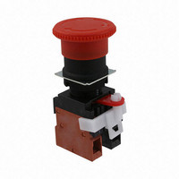
A22E-M-11
Description
Non-lighted,push-lock,turnrese
Manufacturer
Omron
Series
A22r
Type
Emergency Stopr
Specifications of A22E-M-11
Circuit
DPST (1-NO, 1-NC)
Switch Function
On-Off, Off-On
Contact Rating @ Voltage
10A @ 110VAC
Actuator Type
Mushroom Button
Mounting Type
Panel Mount
Termination Style
Screw Terminal
Contact Form
SPST - NC-NO
Contact Rating
10 Amps at 110 Volts
Actuator
Round, Medium
Mounting Style
Through Hole
Illumination
Not Illuminated
Body Shape
Square
Dielectric Strength
2500 Volts
Features
Easy mounting and removal of switch unit
Insulation Resistance
100 MOhms
Mounting Angle
Straight
Water / Moisture Rating
IP65
Contact Configuration
SPST-NO / SPST-NC
Switch Operation
Pushlock Turn Reset
Contact Voltage Ac Nom
440V
Contact Voltage Dc Nom
380V
Contact Current Max
10A
Actuator Style
Round
Lead Free Status / RoHS Status
Lead free / RoHS Compliant
Illumination Type, Color
-
Illumination Voltage (nominal)
-
Lead Free Status / Rohs Status
Lead free / RoHS Compliant
Other names
A22E-M-11
A22EM11
Z3129
A22EM11
Z3129


Wiring
Operating Environment
LEDs
• Terminal screws must be Phillips or slotted M3.5 screws with a
• The tightening torque is 1.08 to 1.27 N·m.
• Single wires, stranded wires, and crimp terminals can be
• Applicable Wiring Materials:
• After wiring the Switch, maintain an appropriate clearance and
• The IP65 model is designed with a protective structure so that it will
• The Switch is intended for indoor use only. Using the Switch
• The LED current-limiting resistor is built-in, so internal resistance is
• If commercially available LEDs are used, select the ones that meet
• Mis-lighting of the LED
(Circuit example)
In case of using 24 VAC/VDC, Direct lighting
Naked Crimp Terminals
Crimp Terminals with
Insulating Sheaths
square washer.
connected to the Switch.
Twisted strands: 2 mm
Solid wire: 1.6 mm dia. max.
creepage distance.
not sustain damage if it is subjected to water from any direction to
the front of the panel.
outdoor may cause it to fail.
not required.
the following conditions:
Base: BA9S/13
Overall length: 26 mm max.
Power consumption: 2.6 W max.
When DC-specific LEDs are used, wire the Switch so that the X1
terminal is positive.
The LED lights with approx. 0.1 mA or less of micro-current. Take
a countermeasure like adding a resistor to prevent mis-lighting in
parallel to the LED.
The micro-current varies with the machine (leak current or stray
capacity between cables, etc.). Select resistance value and
allowable power consumption that meet the actual current.
LED
lamp
X2
X1
R:10kΩ (1W)
Bleeder resistor
2
max.
20.2 mm max.
16.0 mm max.
8 mm max.
8 mm max.
20.2 mm max.
16.0 mm max.
8 mm dia. max.
8 mm dia. max.
Using the Microload
Contact failure may occur if a Switch designed for a standard load is
used to switch a microload. Use Switches within the application
ranges shown in the following graph. Even within the application
range, insert a contact protection circuit, if necessary, to prevent the
reduction of life expectancy due to extreme wear on the
contacts caused by loads where inrush current occurs when the
contact is opened and closed.
The minimum applicable load is the N-level reference value. This
value indicates the malfunction reference level for the reliability
level of 60% (λ
The equation, λ
malfunction rate is less than 1/2,000,000 with a reliability level of 60%.
Others
• If the panel is to be coated, make sure that the panel meets the
• Due to the structure of the Switch, severe shock or vibration may
specified dimensions after coating.
cause malfunctions or damage to the Switch.
Also, most Switches are made from resin and will be damaged if
they come into contact with sharp objects. Particularly scratches
on the Operation Unit may create visual and operational
obtrusions.
Handle the Switches with care, and do not throw or drop them.
Hammer
60
60
) (conforming to JIS C5003).
30
12
24
= 0.5 x 10
5
0
0.1
0.16 mA
Invalid
area
1 mA
1
1.6 mA
Microload area
−6
Screwdriver
/time indicates that the estimated
10 mA
10
Do not operate the
Switch with hard or
sharp objects.
Do not place or drop
heavy objects on the
Switch.
Do not allow the
Switch to drop and hit
the floor.
Current (mA)
100 mA
100
Standard
load area
Area of
use
1,000
A22E
17
Related parts for A22E-M-11
Image
Part Number
Description
Manufacturer
Datasheet
Request
R

Part Number:
Description:
SWITCH, EMERGENCY STOP, SPST-NC, 440VAC
Manufacturer:
Omron
Datasheet:

Part Number:
Description:
Non-lighted,push-lock,turnrese
Manufacturer:
Omron
Datasheet:
Part Number:
Description:
Non-lighted,push-lock,turnrese
Manufacturer:
Omron
Datasheet:
Part Number:
Description:
ESTOP OP UNIT 40mm P-L,T-R
Manufacturer:
Omron
Datasheet:

Part Number:
Description:
Non-lighted,push-lock,turnrese
Manufacturer:
Omron
Datasheet:
Part Number:
Description:
Non-lighted,push-lock,turnrest
Manufacturer:
Omron
Datasheet:
Part Number:
Description:
Non-Lit, Push-Lock, Turn Reset
Manufacturer:
Omron
Datasheet:

Part Number:
Description:
Non-lighted,push-lock,keyreset
Manufacturer:
Omron
Datasheet:
Part Number:
Description:
ESTOP OP UNIT 60 DIA P-P, T-R
Manufacturer:
Omron
Datasheet:
Part Number:
Description:
ESTOP OP UNIT 30mm P-L,T-R
Manufacturer:
Omron
Datasheet:
Part Number:
Description:
SWITCH PB RND MOM SPST-NO/NC RED
Manufacturer:
Omron
Datasheet:

Part Number:
Description:
SWITCH PB ROUND ALT SPST-NO BLUE
Manufacturer:
Omron
Datasheet:

Part Number:
Description:
SWITCH PB ROUND ALT SPST-NO BLK
Manufacturer:
Omron
Datasheet:

Part Number:
Description:
SWITCH PB ROUND ALT SPST-NO GRN
Manufacturer:
Omron
Datasheet:

Part Number:
Description:
SWITCH PB ROUND ALT SPST-NO RED
Manufacturer:
Omron
Datasheet: