A22Z-B101Y Omron, A22Z-B101Y Datasheet - Page 40
A22Z-B101Y
Manufacturer Part Number
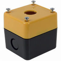
A22Z-B101Y
Description
PB ENCL. 1 HOLE YELLOW
Manufacturer
Omron
Type
Control Boxr
Series
A22r
Specifications of A22Z-B101Y
Accessory Type
Control Box Enclosure
Color
Yellow
Illumination
Not Illuminated
Height
69.5 mm
Length
75 mm
Mounting Style
Panel
Termination Style
Wire
Width
68 mm
Lead Free Status / RoHS Status
Lead free / RoHS Compliant
For Use With/related Products
A22 Series
For Use With
A22EL-M - SWITCH UNIT PB EMRGNCY STOP 40MMA22E-SK - SWITCH UNIT PB EMERGNCY STOP KEYA22E-S - SWITCH UNIT PB EMRGNCY STOP 30MMA22E-MP - SWITCH UNIT PB EMRGNCY STOP 40MMA22E-MK - SWITCH UNIT PB EMERGNCY STOP KEYA22E-M - SWITCH UNIT PB EMRGNCY STOP 40MMA22E-L - SWITCH UNIT PB EMRGNCY STOP 60MMA22EL-M-T2-11 - SWTCH PB EMRGNCY STOP ILLUM SPSTA22EL-M-T2-02 - SWTCH PB EMRGNCY STOP ILLUM DPSTA22EL-M-T2-01 - SWTCH PB EMRGNCY STOP ILLUM SPSTA22EL-M-T1-11 - SWTCH PB EMRGNCY STOP ILLUM SPSTA22EL-M-T1-02 - SWTCH PB EMRGNCY STOP ILLUM DPSTA22EL-M-24A-11 - SWTCH PB EMRGNCY STOP ILLUM SPSTA22EL-M-24A-02 - SWTCH PB EMRGNCY STOP ILLUM DPSTA22EL-M-12A-11 - SWTCH PB EMRGNCY STOP ILLUM SPSTA22EL-M-12A-02 - SWTCH PB EMRGNCY STOP ILLUM DPSTA22EL-M-12A-01 - SWTCH PB EMRGNCY STOP ILLUM SPSTA22E-SK-11 - SWITCH PB EMRGNCY STOP SPST-NO/CA22E-SK-02 - SWITCH PB EMERGENCY STOP DPST-NCZ3128 - SWITCH PB EMRGNCY STOP SPST-NO/CA22E-S-02 - SWITCH PB EMERGENCY STOP DPST-NCA22E-S-01S - SWITCH PB EMERGENCY STOP SPST-NCA22E-MP-02 - SWITCH PB EMERGENCY STOP DPST-NCA22E-MK-02 - SWITCH PB EMERGENCY STOP DPST-NCZ3129 - SWITCH PB EMRGNCY STOP SPST-NO/CA22E-M-02 - SWITCH PB EMERGENCY STOP DPST-NCA22E-LP-11 - SWITCH PB EMRGNCY STOP SPST-NO/CA22E-LP-02 - SWITCH PB EMERGENCY STOP DPST-NCA22E-L-11 - SWITCH PB EMRGNCY STOP SPST-NO/CA22E-L-02 - SWITCH PB EMERGENCY STOP DPST-NCZ1511 - SWTCH PB EMRGNCY SPST-NC ILLZ1510 - SWTCH PB EMRGNCY SPST-NC ILLZ1509 - SWITCH PB EMRGNCY STP SPST-NCZ1508 - SWITCH PB EMRGNCY STP SPST-NCZ1507 - SWITCH PB EMRGNCY SPST-NO/NCZ1506 - SWITCH PB EMRGNCY STP SPST-NCZ1560 - SWITCH PB EMRGNCY SPST-NO/NCZ1505 - SWITCH PB EMRGNCY STP SPST-NCZ1504 - SWITCH PB EMRGNCY STP SPST-NCZ1503 - SWITCH PB EMRGNCY STP SPST-NCZ1502 - SWITCH PB EMRGNCY STP SPST-NC
Lead Free Status / Rohs Status
Lead free / RoHS Compliant
Other names
A22Z-B101Y
A22ZB101Y
Z1648
A22ZB101Y
Z1648


Installation
J MOUNTING THE PANEL
Panel Hole Dimensions
For 25 mm-dia. holes, always use 25 mm-dia. Rings. (Since the
cutout dimensions are large, IP65 cannot be guaranteed unless
25-dia. Rings are used.)
If outer surface treatment such as paint is applied to the panel,
the panel dimensions after outer surface treatment must meet the
specified panel dimensions.
J MATRIX INSTALLATION
Locking should be applied toward the Engraving Plate.
Note: The above dimensions are the smallest-possible mounting
Common To All Assemblies
A
A
22
22
1. The following panel hole dimensions apply when Switch Units
2. The following panel hole dimensions apply when the
Z
Z
and the Standard-size Legend Plate Frame Lock Fitting are
mounted.
Large-size Legend Plate Frame is mounted.
dimensions. However, these dimensions do not apply to
large Pushbutton Switches. For large Pushbutton
Switches, determine the distance between holes, taking
the Operational Unit and Legend Plate Frame into
account.
(0.88)
22.3
(1.18)
(1.18)
30
30
22 dia.
(0.87)
(0.95)
24.1
(1.61)
(1.61)
(0.13)
41
41
3.2
A
22
(0.88)
22.3
N-S
A22N-PR, -MR, -PX
(1.77)
45
(1.18)
30
(0.98)
25
(1.77)
45
25 dia.
(0.98)
(1.77)
45
41
J MOUNTING THE OPERATIONAL UNIT
Insert the Operational Unit from the front surface of the panel,
insert the Lock Fitting and the mounting nut from the terminal
side, then tighten the nut. Before tightening, check that the rubber
washer is present between the Operational Unit and the panel.
When using a Legend Plate Frame, put one rubber washer each
between the Legend Plate Frame and the panel and between the
Operational Unit and the Legend Plate Frame. (One rubber
washer will be provided when one Legend Plate Frame is
ordered.)
Align the Lock Fitting with the groove in the casing, then insert
the Lock Fitting so that its edge is located on the panel side.
Tighten the mounting nut at a torque of 0.98 to 1.96 N • m {10 to
20 kgf • cm}.
When using a Lock Ring, replace with the supplied Lock Fitting,
insert the projecting part into the lock slot, and then tighten the
mounting nut.
When the panel cutout dimension is 25 mm dia., remove the
supplied rubber washer and mount the 25 mm-dia. Ring as
shown below. (Since the A22Z-R25 is not attached to the main
body, order separately.)
Lock Fitting
ON THE PANEL
Panel
Mounting nut
Hold here
22.3 dia.
22.3 dia.
22.3 dia.
25 dia.
25 dia.
25-dia. Ring
Common To All Assemblies
Rubber washer
Operational Unit
Panel
Lock Fitting
(A22Z-R25)
Mounting nut
Proj-
ecting
part
Panel
Lock
Fitting
Related parts for A22Z-B101Y
Image
Part Number
Description
Manufacturer
Datasheet
Request
R

Part Number:
Description:
CONTROL BOX 1 HOLE A22 SERIES
Manufacturer:
Omron
Datasheet:

Part Number:
Description:
CONTROL BOX 2 HOLES A22 SERIES
Manufacturer:
Omron
Datasheet:

Part Number:
Description:
CONTROL BOX 3 HOLES A22 SERIES
Manufacturer:
Omron
Datasheet:

Part Number:
Description:
RING FOR 25MM A22 SERIES PANEL
Manufacturer:
Omron
Datasheet:

Part Number:
Description:
CHARACTER FILM SQUARE A22 SERIES
Manufacturer:
Omron
Datasheet:
Part Number:
Description:
COLOR LENS FOR PB SWITCH BLUE
Manufacturer:
Omron
Datasheet:
Part Number:
Description:
COLOR LENS FOR PB SWITCH GREEN
Manufacturer:
Omron
Datasheet:
Part Number:
Description:
COLOR LENS FOR PB SWITCH RED
Manufacturer:
Omron
Datasheet:
Part Number:
Description:
COLOR LENS FOR PB SWITCH WHITE
Manufacturer:
Omron
Datasheet:
Part Number:
Description:
COLOR LENS FOR PB SWITCH YELLOW
Manufacturer:
Omron
Datasheet:
Part Number:
Description:
SWITCH PB RND MOM SPST-NO/NC RED
Manufacturer:
Omron
Datasheet:

Part Number:
Description:
SWITCH PB ROUND ALT SPST-NO BLUE
Manufacturer:
Omron
Datasheet:

Part Number:
Description:
SWITCH PB ROUND ALT SPST-NO BLK
Manufacturer:
Omron
Datasheet:

Part Number:
Description:
SWITCH PB ROUND ALT SPST-NO GRN
Manufacturer:
Omron
Datasheet:

Part Number:
Description:
SWITCH PB ROUND ALT SPST-NO RED
Manufacturer:
Omron
Datasheet: