6FR40 Vishay, 6FR40 Datasheet - Page 2
6FR40
Manufacturer Part Number
6FR40
Description
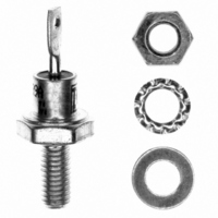
DIODE STD REC 400V 6A DO-4
Manufacturer
Vishay
Datasheet
1.VS-6F60.pdf
(6 pages)
Specifications of 6FR40
Voltage - Forward (vf) (max) @ If
1.1V @ 19A
Voltage - Dc Reverse (vr) (max)
400V
Current - Average Rectified (io)
6A
Current - Reverse Leakage @ Vr
12mA @ 400V
Diode Type
Standard
Speed
Standard Recovery >500ns, > 200mA (Io)
Mounting Type
Chassis, Stud Mount
Package / Case
DO-203AA, DO-4, Stud
Product
Standard Recovery Rectifier
Configuration
Single
Reverse Voltage
400 V
Forward Voltage Drop
1.1 V at 19 A
Forward Continuous Current
6 A
Max Surge Current
167 A
Reverse Current Ir
12000 uA
Mounting Style
Stud
Maximum Operating Temperature
+ 175 C
Minimum Operating Temperature
- 65 C
Lead Free Status / RoHS Status
Lead free / RoHS Compliant
Reverse Recovery Time (trr)
-
Capacitance @ Vr, F
-
Lead Free Status / RoHS Status
Lead free / RoHS Compliant, Lead free / RoHS Compliant
Other names
*6FR40


6F(R) Series
Vishay High Power Products
Note
(1)
www.vishay.com
2
FORWARD CONDUCTION
PARAMETER
Maximum average forward current
at case temperature
Maximum RMS forward current
Maximum non-repetitive peak reverse power
Maximum peak, one cycle forward,
non-repetitive surge current
Maximum I
Maximum I
Low level value of threshold voltage
High level value of threshold voltage
Low level value of forward slope resistance
High level value of forward slope resistance
Maximum forward voltage drop
THERMAL AND MECHANICAL SPECIFICATIONS
PARAMETER
Maximum junction
temperature range
Maximum storage
temperature range
Maximum thermal resistance,
junction to case
Maximum thermal resistance,
case to heatsink
Mounting torque, ± 10 %
Approximate weight
Case style
Available only for avalanche version, all other parameters the same as 6F
2
2
t for fusing
√t for fusing
SYMBOL
R
R
T
T
thCS
thJC
Stg
J
For technical questions, contact: ind-modules@vishay.com
SYMBOL
V
V
I
DC operation
Mounting surface, smooth, flat and greased
Lubricated threads
(Not lubricated threads)
See dimensions - link at the end of datasheet
P
F(RMS)
I
I
F(AV)
F(TO)1
F(TO)2
V
I
Standard Recovery Diodes
FSM
R
I
2
r
r
2
FM
f1
f2
√t
t
(1)
(Stud Version), 6 A
180° conduction, half sine wave
10 µs square pulse, T
t = 10 ms
t = 8.3 ms
t = 10 ms
t = 8.3 ms
t = 10 ms
t = 8.3 ms
t = 10 ms
t = 8.3 ms
t = 0.1 to 10 ms, no voltage reapplied
(16.7 % x π x I
(I > π x I
(16.7 % x π x I
(I > π x I
I
pk
TEST CONDITIONS
= 19 A, T
F(AV)
F(AV)
J
), T
), T
= 25 °C, t
F(AV)
F(AV)
No voltage
reapplied
100 % V
reapplied
No voltage
reapplied
100 % V
reapplied
J
J
TEST CONDITIONS
= T
= T
< I < π x I
< I < π x I
J
J
J
maximum
maximum
= T
p
RRM
RRM
= 400 µs rectangular wave
J
maximum
F(AV)
F(AV)
Sinusoidal half wave,
initial T
T
), T
), T
J
maximum
J
J
= T
= T
J
=
J
J
- 65 to 175
- 65 to 200
VALUES
maximum
maximum
(1.5)
0.25
2.5
0.5
1.2
7
DO-203AA (DO-4)
Document Number: 93519
VALUES
1270
0.63
0.86
15.7
1.10
160
159
167
134
141
127
116
9.5
5.6
90
82
6
4
Revision: 29-Sep-08
(lbf · in)
UNITS
N · m
K/W
oz.
°C
g
UNITS
A
K/W
A
mΩ
°C
2
A
A
A
V
V
2
√s
s
Related parts for 6FR40
Image
Part Number
Description
Manufacturer
Datasheet
Request
R

Part Number:
Description:
357-036-542-201 CARDEDGE 36POS DL .156 BLK LOPRO
Manufacturer:
Vishay
Datasheet:
Part Number:
Description:
357-036-542-201 CARDEDGE 36POS DL .156 BLK LOPRO
Manufacturer:
Vishay
Datasheet:
Part Number:
Description:
357-036-542-201 CARDEDGE 36POS DL .156 BLK LOPRO
Manufacturer:
Vishay
Datasheet:
Part Number:
Description:
357-036-542-201 CARDEDGE 36POS DL .156 BLK LOPRO
Manufacturer:
Vishay
Datasheet:
Part Number:
Description:
357-036-542-201 CARDEDGE 36POS DL .156 BLK LOPRO
Manufacturer:
Vishay
Datasheet:
Part Number:
Description:
357-036-542-201 CARDEDGE 36POS DL .156 BLK LOPRO
Manufacturer:
Vishay
Datasheet:
Part Number:
Description:
357-036-542-201 CARDEDGE 36POS DL .156 BLK LOPRO
Manufacturer:
Vishay
Datasheet:
Part Number:
Description:
357-036-542-201 CARDEDGE 36POS DL .156 BLK LOPRO
Manufacturer:
Vishay
Datasheet:
Part Number:
Description:
357-036-542-201 CARDEDGE 36POS DL .156 BLK LOPRO
Manufacturer:
Vishay
Datasheet:
Part Number:
Description:
357-036-542-201 CARDEDGE 36POS DL .156 BLK LOPRO
Manufacturer:
Vishay
Datasheet:
Part Number:
Description:
357-036-542-201 CARDEDGE 36POS DL .156 BLK LOPRO
Manufacturer:
Vishay
Datasheet:
Part Number:
Description:
357-036-542-201 CARDEDGE 36POS DL .156 BLK LOPRO
Manufacturer:
Vishay
Datasheet:
Part Number:
Description:
357-036-542-201 CARDEDGE 36POS DL .156 BLK LOPRO
Manufacturer:
Vishay
Datasheet:
Part Number:
Description:
357-036-542-201 CARDEDGE 36POS DL .156 BLK LOPRO
Manufacturer:
Vishay
Datasheet:
Part Number:
Description:
357-036-542-201 CARDEDGE 36POS DL .156 BLK LOPRO
Manufacturer:
Vishay
Datasheet: