30CPF12 Vishay, 30CPF12 Datasheet - Page 3
30CPF12
Manufacturer Part Number
30CPF12
Description
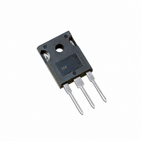
DIODE FAST REC 1200V 30A TO247AC
Manufacturer
Vishay
Datasheet
1.30EPF10.pdf
(8 pages)
Specifications of 30CPF12
Voltage - Forward (vf) (max) @ If
1.41V @ 30A
Voltage - Dc Reverse (vr) (max)
1200V (1.2kV)
Current - Average Rectified (io)
30A
Current - Reverse Leakage @ Vr
100µA @ 1200V
Diode Type
Standard
Speed
Fast Recovery =< 500ns, > 200mA (Io)
Reverse Recovery Time (trr)
450ns
Mounting Type
Through Hole, Radial
Package / Case
TO-247-3 (Straight Leads), TO-247AC
Product
Fast Recovery Rectifier
Configuration
Single Dual Anode
Reverse Voltage
1200 V
Forward Voltage Drop
1.41 V
Recovery Time
450 ns
Forward Continuous Current
30 A
Max Surge Current
350 A
Reverse Current Ir
100 uA
Mounting Style
Through Hole
Maximum Operating Temperature
+ 150 C
Minimum Operating Temperature
- 40 C
Lead Free Status / RoHS Status
Contains lead / RoHS non-compliant
Capacitance @ Vr, F
-
Lead Free Status / RoHS Status
Contains lead / RoHS non-compliant, Lead free / RoHS Compliant
Other names
*30CPF12
VS-30CPF12
VS-30CPF12
VS30CPF12
VS30CPF12
VS-30CPF12
VS-30CPF12
VS30CPF12
VS30CPF12
Available stocks
Company
Part Number
Manufacturer
Quantity
Price


Document Number: 93146
Thermal-Mechanical Specifications
T
T
R
R
R
wt
T
stg
J
thJC
thJA
thCS
150
140
130
120
110
100
60
50
40
30
20
10
90
80
Max. Junction Temperature Range
Max. Storage Temperature Range
Max. Thermal Resistance Junction
to Case
Max. Thermal Resistance Junction
to Ambient
Typical Thermal Resistance, Case to
Heatsink
Approximate Weight
Mounting Torque
Case Style
0
Parameters
Fig. 3 - Forward Power Loss Characteristics
0
0
Fig. 1 - Current Rating Characteristics
180°
120°
RMS Limit
5
5
90°
60°
30°
Average Forward Current (A)
Average Forward Current (A)
10
10
30°
15
15
30.PF.. Series
R
thJC
60°
20
20
(DC) = 0.8 K/W
Conduction Angle
Conduction Angle
30.PF.. Series
T = 150°C
90°
J
Min.
Max.
25
25
120°
180°
30
30
- 40 to 150
- 40 to 150
30.PF..
6 (0.21)
12 (10)
35
35
6 (5)
TO-247AC
0.8
0.2
40
g (oz.)
Kg-cm
(Ibf-in)
Units
°C/W
°C/W
°C/W
30EPF.. 30CPF.. HV
°C
°C
JEDEC (Modified)
DC operation
Mounting surface , smooth and greased
Conditions
150
140
130
120
110
100
80
70
60
50
40
30
20
10
90
80
0
Fig. 4 - Forward Power Loss Characteristics
0
0
RMS Limit
Fig. 2 - Current Rating Characteristics
Preliminary Data Sheet I2138 09/97
180°
120°
90°
60°
30°
DC
Average Forward Current (A)
Average Forward Current (A)
10
10
30°
60°
20
20
30.PF.. Series
R
90°
thJC
120°
www.vishay.com
Conduction Period
30
30
(DC) = 0.8 K/W
30.PF.. Series
T = 150°C
Conduction Period
IR
180°
J
Series
40
40
DC
50
50
3
Related parts for 30CPF12
Image
Part Number
Description
Manufacturer
Datasheet
Request
R

Part Number:
Description:
30 A, 200 V Ultrafast Rectifier, TO-247
Manufacturer:
MULTICOMP
Datasheet:
Part Number:
Description:
30 A, 600 V Ultrafast Rectifier, TO-247
Manufacturer:
MULTICOMP
Datasheet:
Part Number:
Description:
30 A, 40V Schottky Rectifier, TO-220 3 LEAD STANDARD
Manufacturer:
MULTICOMP
Datasheet:
Part Number:
Description:
30 A, 45V Schottky Rectifier, TO-220 3 LEAD FULLPAK
Manufacturer:
MULTICOMP
Datasheet:

Part Number:
Description:
357-036-542-201 CARDEDGE 36POS DL .156 BLK LOPRO
Manufacturer:
Vishay
Datasheet:
Part Number:
Description:
357-036-542-201 CARDEDGE 36POS DL .156 BLK LOPRO
Manufacturer:
Vishay
Datasheet:
Part Number:
Description:
357-036-542-201 CARDEDGE 36POS DL .156 BLK LOPRO
Manufacturer:
Vishay
Datasheet:
Part Number:
Description:
357-036-542-201 CARDEDGE 36POS DL .156 BLK LOPRO
Manufacturer:
Vishay
Datasheet:
Part Number:
Description:
357-036-542-201 CARDEDGE 36POS DL .156 BLK LOPRO
Manufacturer:
Vishay
Datasheet:
Part Number:
Description:
357-036-542-201 CARDEDGE 36POS DL .156 BLK LOPRO
Manufacturer:
Vishay
Datasheet:
Part Number:
Description:
357-036-542-201 CARDEDGE 36POS DL .156 BLK LOPRO
Manufacturer:
Vishay
Datasheet:
Part Number:
Description:
357-036-542-201 CARDEDGE 36POS DL .156 BLK LOPRO
Manufacturer:
Vishay
Datasheet:
Part Number:
Description:
357-036-542-201 CARDEDGE 36POS DL .156 BLK LOPRO
Manufacturer:
Vishay
Datasheet:
Part Number:
Description:
357-036-542-201 CARDEDGE 36POS DL .156 BLK LOPRO
Manufacturer:
Vishay
Datasheet:
Part Number:
Description:
357-036-542-201 CARDEDGE 36POS DL .156 BLK LOPRO
Manufacturer:
Vishay
Datasheet: