1N1205A Vishay, 1N1205A Datasheet - Page 2
1N1205A
Manufacturer Part Number
1N1205A
Description
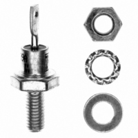
DIODE STD REC 500V 12A DO-4
Manufacturer
Vishay
Datasheet
1.1N1206A.pdf
(5 pages)
Specifications of 1N1205A
Diode Type
Standard
Voltage - Forward (vf) (max) @ If
1.35V @ 12A
Voltage - Dc Reverse (vr) (max)
500V
Current - Average Rectified (io)
12A
Current - Reverse Leakage @ Vr
1.25mA @ 500V
Speed
Standard Recovery >500ns, > 200mA (Io)
Mounting Type
Chassis, Stud Mount
Package / Case
DO-203AA, DO-4, Stud
Repetitive Reverse Voltage Vrrm Max
500V
Forward Current If(av)
12A
Forward Voltage Vf Max
1.35V
Forward Surge Current Ifsm Max
240A
Product
Standard Recovery Rectifier
Configuration
Single
Reverse Voltage
500 V
Forward Voltage Drop
1.35 V
Forward Continuous Current
12 A
Max Surge Current
240 A
Reverse Current Ir
1250 uA
Mounting Style
Through Hole
Lead Free Status / RoHS Status
Lead free / RoHS Compliant
Reverse Recovery Time (trr)
-
Capacitance @ Vr, F
-
Lead Free Status / Rohs Status
Details
Other names
*1N1205A


1N1...A, 1N36..A Series
Vishay High Power Products
Notes
(1)
(2)
(3)
www.vishay.com
2
FORWARD CONDUCTION
PARAMETER
Maximum average forward current
at case temperature
Maximum peak one cycle
non-repetitive surge current
Maximum I
Maximum I
device fusing
Maximum I
device fusing
Maximum forward voltage drop
Maximum average
reverse current
JEDEC registered values
I
Maximum peak reverse current (I
2
t for time t
2
2
2
t for fusing
t for individual
√t for individual
x
= I
2
√t x √t
V
x
V
V
V
V
V
V
V
V
V
V
RRM
V
RRM
RRM
RRM
RRM
RRM
RRM
RRM
RRM
RRM
RRM
RRM
= 1000
= 100
= 150
= 200
= 300
= 400
= 500
= 600
= 700
= 800
= 900
= 50
RM
) under same conditions ≈ 2 x rated I
SYMBOL
I
R(AV)
For technical questions, contact: ind-modules@vishay.com
I
I
2
I
V
F(AV)
FSM
√t
I
2
FM
t
(2)
(3)
Silicon Rectifier Diodes, 12 A
180° sinusoidal conduction
Half cycle 50 Hz sine wave
or 6 ms rectangular pulse
Half cycle 60 Hz sine wave
or 5 ms rectangular pulse
Half cycle 50 Hz sine wave
or 6 ms rectangular pulse
Half cycle 60 Hz sine wave
or 5 ms rectangular pulse
t = 10 ms
t = 8.3 ms
t = 10 ms
t = 8.3 ms
t = 0.1 to 10 ms, V
I
Maximum rated I
F(AV)
= 12 A (38 A peak), T
Medium Power
F(AV)
TEST CONDITIONS
RRM
and T
R(AV)
= 0 following surge
C
C
= 25 °C
Following any rated load
condition and with rated
V
Following any rated load
condition and with V
applied following surge = 0
With rated V
following surge,
initial T
With V
surge, initial T
RRM
applied
RRM
J
= 200 °C
= 0 following
RRM
J
= 200 °C
applied
RRM
VALUES
1.35
2.25
1.75
1.25
150
240
3.0
2.5
2.0
1.5
1.0
0.9
0.8
0.7
0.6
12
3715
Document Number: 93493
230
275
285
260
240
370
340
(1)
(1)
(1)
(1)
(1)
(1)
(1)
(1)
(1)
(1)
(1)
(1)
(1)
(1)
(1)
(1)
Revision: 24-Jun-08
UNITS
A
A
mA
°C
2
A
A
V
2
√s
s
Related parts for 1N1205A
Image
Part Number
Description
Manufacturer
Datasheet
Request
R

Part Number:
Description:
357-036-542-201 CARDEDGE 36POS DL .156 BLK LOPRO
Manufacturer:
Vishay
Datasheet:
Part Number:
Description:
357-036-542-201 CARDEDGE 36POS DL .156 BLK LOPRO
Manufacturer:
Vishay
Datasheet:
Part Number:
Description:
357-036-542-201 CARDEDGE 36POS DL .156 BLK LOPRO
Manufacturer:
Vishay
Datasheet:
Part Number:
Description:
357-036-542-201 CARDEDGE 36POS DL .156 BLK LOPRO
Manufacturer:
Vishay
Datasheet:
Part Number:
Description:
357-036-542-201 CARDEDGE 36POS DL .156 BLK LOPRO
Manufacturer:
Vishay
Datasheet:
Part Number:
Description:
357-036-542-201 CARDEDGE 36POS DL .156 BLK LOPRO
Manufacturer:
Vishay
Datasheet:
Part Number:
Description:
357-036-542-201 CARDEDGE 36POS DL .156 BLK LOPRO
Manufacturer:
Vishay
Datasheet:
Part Number:
Description:
357-036-542-201 CARDEDGE 36POS DL .156 BLK LOPRO
Manufacturer:
Vishay
Datasheet:
Part Number:
Description:
357-036-542-201 CARDEDGE 36POS DL .156 BLK LOPRO
Manufacturer:
Vishay
Datasheet:
Part Number:
Description:
357-036-542-201 CARDEDGE 36POS DL .156 BLK LOPRO
Manufacturer:
Vishay
Datasheet:
Part Number:
Description:
357-036-542-201 CARDEDGE 36POS DL .156 BLK LOPRO
Manufacturer:
Vishay
Datasheet:
Part Number:
Description:
357-036-542-201 CARDEDGE 36POS DL .156 BLK LOPRO
Manufacturer:
Vishay
Datasheet:
Part Number:
Description:
357-036-542-201 CARDEDGE 36POS DL .156 BLK LOPRO
Manufacturer:
Vishay
Datasheet:
Part Number:
Description:
357-036-542-201 CARDEDGE 36POS DL .156 BLK LOPRO
Manufacturer:
Vishay
Datasheet:
Part Number:
Description:
357-036-542-201 CARDEDGE 36POS DL .156 BLK LOPRO
Manufacturer:
Vishay
Datasheet: