D4E-1B10N Omron, D4E-1B10N Datasheet - Page 12
D4E-1B10N
Manufacturer Part Number
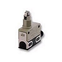
D4E-1B10N
Description
LSW, CROSS RLR PLGR, DC CONCTR
Manufacturer
Omron
Series
D4E-xNr
Specifications of D4E-1B10N
Circuit
SPDT
Switch Function
On-Mom
Contact Rating @ Voltage
1A @ 125VAC
Actuator Type
Roller Plunger
Mounting Type
Chassis Mount
Termination Style
Connector
Operating Force
1177gf
Lead Free Status / RoHS Status
Lead free / RoHS Compliant
Lead Free Status / RoHS Status
Lead free / RoHS Compliant
Other names
D4E1B10N


Precautions
Refer to the “Precautions for General-purpose Limit Switches (Including Multiple Limit Switches, Mechanical Touch Switches, High-precision
Switches, Touch Switches, On-site Flexible Switches; Not Including Safety Switches)” on page 17.
Operating Environment
Seal material may deteriorate if a Switch is used outdoor or where
subject to special cutting oils, solvents, or chemicals. Always
appraise performance under actual application conditions and set
suitable maintenance and replacement periods.
Install Switches where they will not be directly subject to cutting
chips, dust, or dirt. The Actuator and Switch must also be protected
from the accumulation of cutting chips or sludge.
Constantly subjecting a Switch to vibration or shock can result in
wear, which can lead to contact interference with contacts, operation
failure, reduced durability, and other problems. Excessive vibration or
shock can lead to false contact operation or damage. Install Switches
in locations not subject to shock and vibration and in orientations that
will not produce resonance.
The Switches have physical contacts. Using them in environments
containing silicon gas will result in the formation of silicon oxide
(SiO
tacts, contact interference can occur. If silicon oil, silicon filling
agents, silicon cables, or other silicon products are present near the
Switch, suppress arcing with contact protective circuits (surge killers)
or remove the source of silicon gas.
Do not solder the screw terminals.
Sealing materials may deteriorate when used outdoors or when
exposed to cutting oil, solvents, or chemicals. Check this on actual
equipment and, if deterioration is foreseen, consult your OMRON
representative in advance.
If the one-touch connector is to be mounted onto the switch body,
lightly push up the fitting so that the switch body can then be inserted
into the clamp.
Be sure that the clamp is inserted to the full depth, because the
Switch will not function properly if one of the clamps is improperly
inserted.
Not Suitable
Correct Use
2
) due to arc energy. If silicon oxide accumulates on the con-
Insert the switch
body
Switch body
Clamp fitting
Lightly push up the filling on the
left and right side alternately.
Suitable
Confirm
visually
If the clamp is properly inserted up to the full depth, it will not slide
out easily. Be sure to carefully confirm all the above items.
Be sure to connect a fuse with a breaking current 1.5 to 2 times the
rated current to the Limit Switch in series in order to protect the Limit
Switch from damage due to short-circuiting.
When using the Limit under the EN ratings, use a gI or gG 10-A fuse
that conforms to IEC269.
Mounting
Secure the Switch with two M4 screws and washers. The tightening
torque applied to each terminal must be 1.18 to 1.37 N·m. Tighten
the screws to the specified torque. An excessive tightening torque
may damage the Switch and cause a malfunction.
Mounting Holes
When mounting the panel mount-type Switch with screws on a side
surface, remove the hexagonal nuts from the actuator.
When mounting the panel mount type on a panel, tighten the hexag-
onal nuts of the actuator to a torque less than 7.85 N·m.
Mounting Hole
Operating method, shape of cam or dog, operating frequency, and
the overtravel (OT) have significant effect on the service life and pre-
cision of the Limit Switch. Make sure that the shape of the cam is
smooth enough.
Check that OT has a sufficient margin. The actual OT should be
rated OT x 0.7 to 1.
Do not change the operating position by remodeling the actuator.
Wiring
When wiring screw terminals, M3-size round solderless terminals
with an insulation tube is recommended. The conductor size should
be 0.75 mm
Refer to the following when wiring.
dz dia.: 3.2
D dia.:
B:
L:
F:
l:
2
Small Sealed Switch
1.9
5.2
16.4
5.8
8.0 (mm)
and cable diameter should be 7 mm.
D dia.
Two, 4.3 dia. or M4 hole
33±0.15
14.5±0.2 dia.
d
D4E-@N
z
dia.
149
Related parts for D4E-1B10N
Image
Part Number
Description
Manufacturer
Datasheet
Request
R

Part Number:
Description:
SWITCH SPDT 5A 125V ROLLER PLNGR
Manufacturer:
Omron
Datasheet:

Part Number:
Description:
LS, GEN OUR, RLR PLGR, W/CABLE
Manufacturer:
Omron
Datasheet:
Part Number:
Description:
LSW, CROSS RLR PLGR, AC CONCTR
Manufacturer:
Omron
Datasheet:
Part Number:
Description:
LSW, CROSS RLR PLGR, W/O CABLE
Manufacturer:
Omron
Datasheet:
Part Number:
Description:
LSW, CROSS RLR PLGR, W/CABLE
Manufacturer:
Omron
Datasheet:
Part Number:
Description:
LSW, PLUNGER, DC CONNECTOR
Manufacturer:
Omron
Datasheet:
Part Number:
Description:
LSW, SEALED ROLLER PLUNGER
Manufacturer:
Omron
Datasheet:
Part Number:
Description:
MiniLS,Seal Roller Plunger3mCb
Manufacturer:
Omron
Datasheet:
Part Number:
Description:
LIMIT SWITCH
Manufacturer:
Omron
Datasheet:
Part Number:
Description:
SWITCH SPDT 5A 125V ROLLER PLNGR
Manufacturer:
Omron
Datasheet:
Part Number:
Description:
SWITCH SPDT 5A 125V ROLLER PLNGR
Manufacturer:
Omron
Datasheet:
Part Number:
Description:
SWITCH SPDT 5A 125V ROLLER PLNGR
Manufacturer:
Omron
Datasheet:
Part Number:
Description:
SWITCH SPDT 5A 125V ROLLER LEVER
Manufacturer:
Omron
Datasheet:
Part Number:
Description:
SWITCH SPDT 5A 125V ROLLER PLNGR
Manufacturer:
Omron
Datasheet: