6F100 Vishay, 6F100 Datasheet - Page 4
6F100
Manufacturer Part Number
6F100
Description
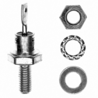
DIODE STD REC 1000V 6A DO-4
Manufacturer
Vishay
Datasheet
1.VS-6F60.pdf
(6 pages)
Specifications of 6F100
Diode Type
Standard
Voltage - Forward (vf) (max) @ If
1.1V @ 19A
Voltage - Dc Reverse (vr) (max)
1000V (1kV)
Current - Average Rectified (io)
6A
Current - Reverse Leakage @ Vr
12mA @ 1000V
Speed
Standard Recovery >500ns, > 200mA (Io)
Mounting Type
Chassis, Stud Mount
Package / Case
DO-203AA, DO-4, Stud
Product
Standard Recovery Rectifier
Configuration
Single
Reverse Voltage
1000 V
Forward Voltage Drop
1.1 V at 19 A
Forward Continuous Current
6 A
Max Surge Current
167 A
Reverse Current Ir
12000 uA
Mounting Style
Stud
Maximum Operating Temperature
+ 175 C
Minimum Operating Temperature
- 65 C
Repetitive Reverse Voltage Vrrm Max
1kV
Forward Current If(av)
16A
Forward Voltage Vf Max
1.1V
Forward Surge Current Ifsm Max
141A
Lead Free Status / RoHS Status
Lead free / RoHS Compliant
Reverse Recovery Time (trr)
-
Capacitance @ Vr, F
-
Lead Free Status / RoHS Status
Lead free / RoHS Compliant, Lead free / RoHS Compliant
Other names
*6F100


6F(R) Series
Vishay High Power Products
www.vishay.com
4
Fig. 5 - Maximum Non-Repetitive Surge Current
Fig. 6 - Maximum Non-Repetitive Surge Current
150
140
130
120
110
100
160
150
140
130
120
110
100
90
80
70
60
50
40
30
90
80
70
60
50
40
Number Of Equal Amplitude Half Cycle Current Pulses (N)
0.01
1
Maximum Non Repetitive Surge Current
6F(R) Series
6F(R) Series
At Any Rated Load Condition And With
Rated V
Pulse Train Duration (s)
RRM
Versus Pulse Train Duration.
8
7
6
5
4
3
2
1
0
Applied Following Surge.
0
Rated V
RMS Limit
0.1
10
No Voltage Reapplied
@ 60 Hz 0.0083 s
@ 50 Hz 0.0100 s
180°
120°
Initial T = 175°C
Initial T = 175°C
Average Forward Current (A)
90°
60°
30°
DC
2
RRM
For technical questions, contact: ind-modules@vishay.com
J
Reapplied
J
4
Fig. 4 - Forward Power Loss Characteristics
Standard Recovery Diodes
100
1
Conduction Period
6
6F(R) Series
T = 175°C
J
(Stud Version), 6 A
8
10
0
Maximum Allowable Ambient Temperature (°C)
25
Fig. 8 - Thermal Impedance Z
1000
50
100
Fig. 7 - Forward Voltage Drop Characteristics
0.1
10
10
0.001
1
1
0
Steady State Value
R
(DC Operation)
6F(R) Series
thJC
Instantaneous Forward Voltage (V)
75
Square Wave Pulse Duration (s)
0.5
0.01
= 2.5 K/W
100
1
0.1
6F(R) Series
T = 25°C
T = 175°C
1.5
J
J
Document Number: 93519
thJC
1
Characteristics
Revision: 29-Sep-08
2
2.5
10
Related parts for 6F100
Image
Part Number
Description
Manufacturer
Datasheet
Request
R

Part Number:
Description:
DIODE STD REC 100V 6A DO-4
Manufacturer:
Vishay
Datasheet:

Part Number:
Description:
357-036-542-201 CARDEDGE 36POS DL .156 BLK LOPRO
Manufacturer:
Vishay
Datasheet:
Part Number:
Description:
357-036-542-201 CARDEDGE 36POS DL .156 BLK LOPRO
Manufacturer:
Vishay
Datasheet:
Part Number:
Description:
357-036-542-201 CARDEDGE 36POS DL .156 BLK LOPRO
Manufacturer:
Vishay
Datasheet:
Part Number:
Description:
357-036-542-201 CARDEDGE 36POS DL .156 BLK LOPRO
Manufacturer:
Vishay
Datasheet:
Part Number:
Description:
357-036-542-201 CARDEDGE 36POS DL .156 BLK LOPRO
Manufacturer:
Vishay
Datasheet:
Part Number:
Description:
357-036-542-201 CARDEDGE 36POS DL .156 BLK LOPRO
Manufacturer:
Vishay
Datasheet:
Part Number:
Description:
357-036-542-201 CARDEDGE 36POS DL .156 BLK LOPRO
Manufacturer:
Vishay
Datasheet:
Part Number:
Description:
357-036-542-201 CARDEDGE 36POS DL .156 BLK LOPRO
Manufacturer:
Vishay
Datasheet:
Part Number:
Description:
357-036-542-201 CARDEDGE 36POS DL .156 BLK LOPRO
Manufacturer:
Vishay
Datasheet:
Part Number:
Description:
357-036-542-201 CARDEDGE 36POS DL .156 BLK LOPRO
Manufacturer:
Vishay
Datasheet:
Part Number:
Description:
357-036-542-201 CARDEDGE 36POS DL .156 BLK LOPRO
Manufacturer:
Vishay
Datasheet:
Part Number:
Description:
357-036-542-201 CARDEDGE 36POS DL .156 BLK LOPRO
Manufacturer:
Vishay
Datasheet:
Part Number:
Description:
357-036-542-201 CARDEDGE 36POS DL .156 BLK LOPRO
Manufacturer:
Vishay
Datasheet:
Part Number:
Description:
357-036-542-201 CARDEDGE 36POS DL .156 BLK LOPRO
Manufacturer:
Vishay
Datasheet: