E2E2-X8MD2 Omron, E2E2-X8MD2 Datasheet - Page 7
E2E2-X8MD2
Manufacturer Part Number
E2E2-X8MD2
Description
PROX LONG M12,8MM DC2W-NC 2M
Manufacturer
Omron
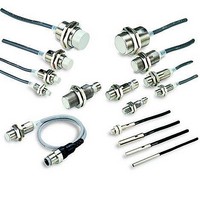
Type
Inductive Proximity Sensorr
Specifications of E2E2-X8MD2
Maximum Operating Temperature
+ 70 C
Supply Voltage
10 V to 30 V
Mounting Style
Screw
Sensing Distance
8 mm
Minimum Operating Temperature
- 25 C
Features
NC
Lead Free Status / Rohs Status
Lead free / RoHS Compliant


E2E2 2-WIRE DC
J INSTALLATION
Power Reset Time
The Proximity Sensor is ready to operate within 100 ms after power
is supplied. If power supplies are connected to the Proximity Sensor
and load respectively, be sure to supply power to the Proximity Sen-
sor before supplying power to the load.
Power OFF
The Proximity Sensor may output a pulse signal when it is turned off.
Turn off the load before turning off the Proximity Sensor.
Power Supply Transformer
When using a DC power supply, make sure that the DC power sup-
ply has an insulated transformer. Do not use a DC power supply with
an auto-transformer.
Target Object
Metal Coating
The sensing distances of the Proximity Sensor vary with the metal
coating on target objects.
J WIRING
High-tension Lines
Wiring through Metal Conduit
If there is a power or high-tension line near the cable of the Proximity
Sensor, wire the cord through an independent metal conduit to pre-
vent against Proximity Sensor damage or malfunctioning.
J CONNECTING LOAD
Refer to the following before using DC 2-wire Proximity Sensors.
Surge Protection
Although the Proximity Sensor has a surge absorption circuit, if
there is any machine that has a large surge current (e.g., a motor or
welding machine) near the Proximity Sensor, connect a surge ab-
sorber to the machine.
Leakage Current
When the Proximity Sensor is OFF, the Proximity Sensor has leak-
age current. Refer to Leakage Current Characteristics. In this case,
the load is imposed with a small voltage and the load may not be re-
set. Before using the Proximity Sensor, make sure that this voltage
is less than the load reset voltage.
Countermeasures Against Leakage Current
DC 2-wire Models
Connect a bleeder resistor as the bypass for the leakage current so
that the current flowing into the load will be less than the load reset
current.
Bleeder resistor R
Load
8
Cable Tractive Force
Do not pull cables with the tractive forces exceeding the following.
J MOUNTING
The Proximity Sensor must not be subjected to excessive shock
with a hammer when it is installed, or the Proximity Sensor may be
damaged or lose its water-resistance.
J ENVIRONMENT
Water Resistance
Do not use the Proximity Sensor underwater, outdoors, or in the
rain.
Operating Environment
Be sure to use the Proximity Sensor within its operating ambient
temperature range and do not use the Proximity Sensor outdoors so
that its reliability and life expectancy can be maintained. Although
the Proximity Sensor is water resistant, a cover to protect the Prox-
imity Sensor from water or water soluble machining oil is recom-
mended so that its reliability and life expectancy can be maintained.
Do not use the Proximity Sensor in an environment with chemical
gas (e.g., strong alkaline or acid gasses including nitric, chromic,
and concentrated sulfuric acid gases).
Refer to the following to calculate the bleeder resistance and the al-
lowable power of the bleeder resistor.
R ≦ V
P > V
P: The allowable power of the bleeder resistor. (The actual power
i
i
The following resistors are recommended.
12 VDC (supply voltage): A resistor with a resistance of 15 kΩ maxi-
mum and an allowable power of 450 mW minimum
24 VDC (supply voltage): A resistor with a resistance of 30 kΩ maxi-
mum and an allowable power of 0.1 W minimum
Inrush Current
A load that has a large inrush current (e.g., a lamp or motor) will
damage the Proximity Sensor, in which case connect the load to the
Proximity Sensor through a relay.
R
OFF
Diameter
4 mm dia. max.
4 mm dia. min.
: Leakage current of Sensors (mA)
capacity of the bleeder resistor must be at least a few times as
large as the allowable power of the bleeder resistor.)
: Release current of load (mA)
S
S
2
/(i
/R (mW)
R
- - i
OFF
) (kΩ)
Tractive force
30 N max.
50 N max.
E2E2 2-WIRE DC
Related parts for E2E2-X8MD2
Image
Part Number
Description
Manufacturer
Datasheet
Request
R

Part Number:
Description:
E2E2-X5MB1 W/ M12 CONNECTOR
Manufacturer:
Omron
Datasheet:

Part Number:
Description:
PROX LONG M30, 10mm NPN-NC 2M
Manufacturer:
Omron
Datasheet:
Part Number:
Description:
PROX LONG M18, 10mm PNP-NO 2M
Manufacturer:
Omron
Datasheet:
Part Number:
Description:
PROX LONG M18,10mm NPN-NO 2M
Manufacturer:
Omron
Datasheet:

Part Number:
Description:
PROX LONG M30,10mm AC2W-NO(COO
Manufacturer:
Omron
Datasheet:
Part Number:
Description:
PROX LONG M12,2mm NPN-NC 2M
Manufacturer:
Omron
Datasheet:
Part Number:
Description:
PROX LONG M12,2mm AC2W-NC 2M
Manufacturer:
Omron
Datasheet:
Part Number:
Description:
PROX LONG M18,5mm NPN-NC 2M
Manufacturer:
Omron
Datasheet: