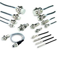
E2EM-X2B1-M1 Omron, E2EM-X2B1-M1 Datasheet - Page 13

E2EM-X2B1-M1
Manufacturer Part Number
E2EM-X2B1-M1
Description
EXTND M8 SHD PNP-NO 2MM M12
Manufacturer
Omron
Type
Inductive Proximity Sensorr
Series
E2EMr
Datasheet
1.E2EM-X15C1-M1.pdf
(15 pages)
Specifications of E2EM-X2B1-M1
Proximity Sensor Type
Inductive
Output Type
PNP
Proximity Sensor Sensing Distance
2mm
Proximity Sensor Sensing Distance Range
2 to 7mm
Proximity Sensor Switching Mode
NO
Mounting
Panel
Operating Temp Range
-25C to 70C
Operating Temperature Classification
Commercial
Operating Supply Voltage (min)
10V
Operating Supply Voltage (typ)
12/15/18/24V
Operating Supply Voltage (max)
30V
Pin Count
3
Maximum Operating Temperature
+ 70 C
Operating Supply Voltage
10 V to 40 V
Sensing Distance
2 mm
Minimum Operating Temperature
- 25 C
Features
NO
Sensor Type
Inductive
Sensing Object
Metallic
Response Frequency
1.5kHz
Material - Body
Stainless Steel
Shielding
Shielded
Voltage - Supply
10 V ~ 40 V
Terminal Type
Connector
Package / Case
Cylinder, Threaded - M8
Lead Free Status / Rohs Status
Compliant
E2EM
Mutual Interference
When installing two or more Sensors face-to-face or side-by-side,
ensure that the minimum distances given in the following table
are maintained.
(Unit: mm) See note.
J DESIGNING
Confirmation of Connection between DC 2-wire Prox-
imity Sensor and Programmable Controller
Connection conditions are determined from the relationship
between the input ON voltage and OFF voltage of the PC and the
output residual voltage and leakage current of the Proximity
Sensor.
Connection Conditions
Connection is possible under the following conditions.
Example values on the PC side
Example values on the Proximity Sensor side
If these values are put in the above formula, V
as follows:
E2EM-
E2EM
XjXj
XjXj
DC 2-wire
DC 2-wire
E2EM-
XjB/C
XjB/C
DC 3-wire
1. Relationship between the ON voltage of the PC and the
2. Relationship between the OFF voltage of the PC and the
residual voltage of the Proximity Sensor must be as follows:
leakage current of the Proximity Sensor must be as follows:
V
V
V
V
V
V
I
R
ON voltage: 10.2 V min.
OFF voltage: 3 V max.
Input impedance: 3.5 kΩ
Output residual voltage: 5 V max.
Leakage current: 0.8 mA max.
V
V
leak
on
on
cc
R
off
off
on
off
in
: Output residual voltage the Proximity Sensor
: Input impedance of the PC
≦V
: ON voltage of the PC
: 10.2 V<24 V- - 5 V (=19 V)
: Supply voltage
≧I
: OFF voltage of the PC
: 3 V>0.8 mA x 3.5 kΩ (=2.8 V)
: Leakage current of the Proximity Sensor
Type
leak
cc
Shielded
Shielded
Unshielded
Unshielded
Shielded
- - V
x R
R
in
A
B
A
B
A
B
Item
---
20
15
M8
30
20
---
30
20
M12
on
and V
60
35
200
120
60
35
M18
off
will be
110
90
350
300
110
90
M30
14
J WIRING
High-tension Lines
Wiring through Metal Conduit:
If there is a power or high-tension line near the cable of the
Proximity Sensor, wire the cable through an independent metal
conduit to prevent against Proximity Sensor damage or
malfunctioning.
Connections
Note: The residual voltage of the DC 2-wire model is 5 V. Check
Cable Extension
Cable length must be less than 200 m (656 ft.).
The tractive force is 50 N (11.24 lbF).
J MOUNTING
The Proximity Sensor must not be subjected to excessive shock
with a hammer when it is installed, otherwise the Proximity
Sensor may be damaged or lose its water-resistivity.
Do not tighten the nut with excessive force. A washer must be
used with the nut.
DC 2-wire Models
Connection to relay load
DC 3-wire Models
Connection to S3D2 Sensor Controller
Operation can be reversed
by selecting the signal input
selector of the S3D2.
Type
M8
M12
M18
M30
the operating voltage of the relay.
Brown
Blue
Blue 0 V
Brown +12 V
Black OUT
Torque
9 N S m (79.6 in lbF)
30 N S m (265 in lbF)
70 N S m (619 in lbF)
180 N S m (1593 in lbF)
S3D2
24 VDC
E2EM


