HFA16PB120 Vishay, HFA16PB120 Datasheet - Page 5
HFA16PB120
Manufacturer Part Number
HFA16PB120
Description
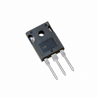
DIODE HEXFRED 1200V 16A TO-247AC
Manufacturer
Vishay
Series
HEXFRED®r
Datasheet
1.HFA16PB120.pdf
(7 pages)
Specifications of HFA16PB120
Voltage - Forward (vf) (max) @ If
3V @ 16A
Voltage - Dc Reverse (vr) (max)
1200V (1.2kV)
Current - Average Rectified (io)
16A
Current - Reverse Leakage @ Vr
20µA @ 1200V
Diode Type
Standard
Speed
Fast Recovery =< 500ns, > 200mA (Io)
Reverse Recovery Time (trr)
135ns
Mounting Type
Through Hole, Radial
Package / Case
TO-247-2 (TO-247AC Modified)
Product
Ultra Fast Recovery Rectifier
Configuration
Single
Reverse Voltage
1200 V
Forward Voltage Drop
3.93 V at 32 A
Recovery Time
135 ns
Forward Continuous Current
16 A
Max Surge Current
190 A
Reverse Current Ir
20 uA
Mounting Style
Through Hole
Maximum Operating Temperature
+ 150 C
Minimum Operating Temperature
- 55 C
Lead Free Status / RoHS Status
Contains lead / RoHS non-compliant
Capacitance @ Vr, F
-
Lead Free Status / RoHS Status
Contains lead / RoHS non-compliant, Lead free / RoHS Compliant
Other names
*HFA16PB120
VS-HFA16PB120
VS-HFA16PB120
VSHFA16PB120
VSHFA16PB120
VS-HFA16PB120
VS-HFA16PB120
VSHFA16PB120
VSHFA16PB120
Available stocks
Company
Part Number
Manufacturer
Quantity
Price
Company:

Part Number:
HFA16PB120
Manufacturer:
IR
Quantity:
10 000
Company:
Part Number:
HFA16PB120PBF
Manufacturer:
MICROCHIP
Quantity:
1 001


Document Number: 93071
Fig. 9 - Reverse Recovery Parameter Test
REVERSE RECOVERY CIRCUIT
ADJUST
dif/dt
L = 70µH
G
Circuit
V
R
= 200V
0.01
D
S
IRFP250
D.U.T.
0
1. di
2. I
3. trr - Reverse recovery time measured
I
through zero crossing
from zero crossing point of negative
going I
through 0.75 I
extrapolated to zero current
F
RRM
f
/dt - Rate of change of current
Fig. 10 - Reverse Recovery Waveform and
- Peak reverse recovery current
F
to point where a line passing
RRM
1
and 0.50 I
di /dt
f
Bulletin PD-2.364 rev. A 11/00
RRM
t
Definitions
a
2
3
I
t
RRM
rr
4. Q
5. di
and I
current during t
rr
(rec)M
0.75 I
- Area under curve defined by t
RRM
t
b
/dt - Peak rate of change of
HFA16PB120
www.vishay.com
RRM
di(rec)M/dt
0.5
Q
rr
Q
=
b
I
rr
RRM
portion of t
t
4
rr
X I
2
RRM
5
rr
rr
5
Related parts for HFA16PB120
Image
Part Number
Description
Manufacturer
Datasheet
Request
R

Part Number:
Description:
Ultra High Slew RateOperational Amplifier
Manufacturer:
Intersil Corporation
Part Number:
Description:
Ultra High Slew Rate Operational Amplifier
Manufacturer:
Intersil Corporation
Part Number:
Description:
Ultra High Speed Comparator
Manufacturer:
Intersil Corporation
Part Number:
Description:
Ultra High Speed Comparator
Manufacturer:
Intersil Corporation

Part Number:
Description:
357-036-542-201 CARDEDGE 36POS DL .156 BLK LOPRO
Manufacturer:
Vishay
Datasheet:
Part Number:
Description:
357-036-542-201 CARDEDGE 36POS DL .156 BLK LOPRO
Manufacturer:
Vishay
Datasheet:
Part Number:
Description:
357-036-542-201 CARDEDGE 36POS DL .156 BLK LOPRO
Manufacturer:
Vishay
Datasheet:
Part Number:
Description:
357-036-542-201 CARDEDGE 36POS DL .156 BLK LOPRO
Manufacturer:
Vishay
Datasheet:
Part Number:
Description:
357-036-542-201 CARDEDGE 36POS DL .156 BLK LOPRO
Manufacturer:
Vishay
Datasheet:
Part Number:
Description:
357-036-542-201 CARDEDGE 36POS DL .156 BLK LOPRO
Manufacturer:
Vishay
Datasheet:
Part Number:
Description:
357-036-542-201 CARDEDGE 36POS DL .156 BLK LOPRO
Manufacturer:
Vishay
Datasheet:
Part Number:
Description:
357-036-542-201 CARDEDGE 36POS DL .156 BLK LOPRO
Manufacturer:
Vishay
Datasheet:
Part Number:
Description:
357-036-542-201 CARDEDGE 36POS DL .156 BLK LOPRO
Manufacturer:
Vishay
Datasheet:
Part Number:
Description:
357-036-542-201 CARDEDGE 36POS DL .156 BLK LOPRO
Manufacturer:
Vishay
Datasheet:
Part Number:
Description:
357-036-542-201 CARDEDGE 36POS DL .156 BLK LOPRO
Manufacturer:
Vishay
Datasheet: