E3C-DS5W Omron, E3C-DS5W Datasheet - Page 9
E3C-DS5W
Manufacturer Part Number
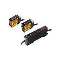
E3C-DS5W
Description
PHOTO SEPARATE AMP
Manufacturer
Omron
Series
E3Cr
Datasheet
1.E3C-GE4.pdf
(16 pages)
Specifications of E3C-DS5W
Sensing Distance
1.969" (50mm)
Sensing Method
Reflective, Diffuse
Sensing Object
White Paper
Output Configuration
-
Sensing Light
Infrared
Mounting Type
Bracket Mount
Current - Supply
-
Voltage - Supply
-
Package / Case
Module, Pre-Wired
Features
Fast Response Time
Lead Free Status / RoHS Status
Lead free / RoHS Compliant
Lead Free Status / RoHS Status
Lead free / RoHS Compliant


Nomenclature/Settings
Amplifier Units
E3C-A
E3C-C
Operation
indicator (red)
When a relay-switch
operates, the indicator turns
on.
Operation
selector
Response
time
selector
switch
Operation indicator
(red)
When a relay-switch
operates, the indicator turns
on.
Operation
selector
Selector
switch for
response
time
Timer
function
setting
switch
Delay
time setting
switch
Timer function setting
When select-
ing ON delay
(ON D.)
When select-
ing OFF de-
lay (OFF D.)
When select-
ing one-shot
delay
(O.S.D.)
Delay time adjuster
DARK ON
DARK ON
DARK ON
Nomenclature
2 ms (B)
2 ms (B)
2 ms (B)
DELAY
DELAY
DELAY
ON D.
ON D.
ON D.
1 sec
1 sec
1 sec
Stability indicator (green)
When the light receiving input
becomes +20% or more and −20%
or less of operating voltage, it will be
turned on. (Indicate stable status)
Sensitivity adjuster
Stability indicator (green)
When the light receiving input
becomes +20% or more and −20%
or less of operating voltage, it will
be turned on. (Indicate stable status)
Sensitivity adjuster
LIGHT ON
1 ms (A)
O.S.D.
OFF D.
10 sec
LIGHT ON
1 ms (A)
O.S.D.
OFF D.
10 sec
LIGHT ON
1 ms (A)
O.S.D.
OFF D.
10 sec
Set a position freely
Set a position freely
Since the function has
stopped, it allows in
both of the positions.
Set a position freely
Set a position freely
Set a position freely
Set a position freely
Set a position freely
Set a position freely
Set a position freely
Light indicator
(red)
When the light
inputs,
it will be turned on.
Light indicator
(red)
When the light
inputs,
it will be turned on.
Operation switching
Response time changing (The different frequency type can be
made up by changing the response speed.)
Timing chart
Operation switching
Response time changing (The different frequency type can be
made up by changing the response speed.)
Delay time setting
Timing chart
External synchronous input operation
When the external synchronous input terminal (9) is open (HIGH), the output
relay performs timer operation according to the input signals (LIGHT, DARK).
When the external synchronous input terminaL (9) is connected to the 0 V ter-
minal (2) (LOW), the output relay turns OFF, independently of the input signals
and output status, and acts as an inhibit signal.
Selector switch for
Selector switch for
Note 1. t must be longer than 1 ms or 2 ms. 2. T denotes a delay time.
DARK ON
DARK ON
DARK ON
DARK ON
External
synchro-
nous in-
puts
ON D.
OFF D.
O.S.D.
No incident light
operating mode
operating mode
2 ms (B)
2 ms (B)
2 ms (B)
2 ms (B)
Min
Incident light
Note 1. Control output is produced only during input time.
1 sec
1 sec
No incident light
LIGHT ON
DARK ON
TIME
Incident light
Short circuit
DARK ON
DARK ON
DARK ON
LIGHT ON
LIGHT ON
LIGHT ON
2. When t exceeds 1 ms or 2 ms, solid-state output is produced.
To produce relay output, t must be longer than 20 ms.
Release
Max
(9)-(2)
(9)(2)
10 sec
10 sec
LIGHT ON
LIGHT ON
LIGHT ON
LIGHT ON
1 ms (A)
1 ms (A)
1 ms (A)
1 ms (A)
After setting the selector, fine-adjust the delay time with the
variable adjuster. (Clockwise turn increases the delay time.)
T
T
T
t
DARK turns the relay ON and the transistor out-
put "H".
LIGHT turns the relay ON and the transistor out-
put "H".
The response time is set to 2 ms.
The response time is set to 1 ms.
DARK turns the relay ON and the transistor out-
put "H".
LIGHT turns the relay ON and the transistor out-
put "H".
The response time is set to 2 ms.
The response time is set to 1 ms.
0.1 to 1 s can be set.
1 to 10 s can be set.
T
T
T
Settings
t
t
T
T
T
T
Relay
"a"
"b"
"a"
"b"
Output
Solid
state
"H"
"H"
"L"
"L"
(Output
transistor)
(OFF)
(ON)
(OFF)
(ON)
Relay Solid
"a"
"b"
"a"
"b"
"a"
"b"
"a"
"b"
"a"
"b"
"a"
"b"
Output
state
"H"
"H"
"H"
"H"
"H"
"H"
"L"
"L"
"L"
"L"
"L"
"L"
(Output
transistor)
(ON)
(OFF)
(ON)
(OFF)
(ON)
(OFF)
(ON)
(OFF)
(ON)
(OFF)
(ON)
(OFF)
E3C
9
Related parts for E3C-DS5W
Image
Part Number
Description
Manufacturer
Datasheet
Request
R

Part Number:
Description:
EMITTER COMPONENT OF E3C-S20W
Manufacturer:
Omron
Datasheet:
Part Number:
Description:
PHOTO DIFFUSE 10CM
Manufacturer:
Omron
Datasheet:
Part Number:
Description:
PHOTO AMPLIFIER DC
Manufacturer:
Omron
Datasheet:
Part Number:
Description:
PHOTO BEAM BREAK 1M
Manufacturer:
Omron
Datasheet:
Part Number:
Description:
AMPLIFIER PNP SLD. ST.
Manufacturer:
Omron
Datasheet:
Part Number:
Description:
AMP,RAIL MT,ALARM OUTPUT
Manufacturer:
Omron
Datasheet:
Part Number:
Description:
PHOTO FOCUSED TYPE 3CM
Manufacturer:
Omron
Datasheet:
Part Number:
Description:
PHOTO SEPARATE AMP
Manufacturer:
Omron
Datasheet:

Part Number:
Description:
PHOTO MARK SENSOR 1CM
Manufacturer:
Omron
Datasheet:

Part Number:
Description:
PES AMP SLIM DIN MOUNT
Manufacturer:
Omron
Datasheet:

Part Number:
Description:
G6S-2GLow Signal Relay
Manufacturer:
Omron Corporation
Datasheet:
Part Number:
Description:
Compact, Low-cost, SSR Switching 5 to 20 A
Manufacturer:
Omron Corporation
Datasheet: