E3S-CT66 Omron, E3S-CT66 Datasheet - Page 13
E3S-CT66
Manufacturer Part Number
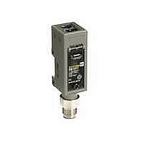
E3S-CT66
Description
VERTICAL, T-BEAM 30M CONN.
Manufacturer
Omron
Series
E3S-Cr
Type
Long Range Metal Body Sensorr
Datasheet
1.E3S-CT11.pdf
(14 pages)
Specifications of E3S-CT66
Sensing Distance
1181.102" (30m)
Sensing Method
Through-Beam
Output Configuration
NPN/PNP - Dark-ON/Light-ON - Selectable
Mounting Type
Bracket Mount, Vertical
Current - Supply
50mA
Voltage - Supply
10 V ~ 30 V
Response Time
1ms
Package / Case
Module, Connector
Features
Mutual interference protection
Height
32.2 mm
Length
74 mm
Maximum Operating Temperature
+ 55 C
Minimum Operating Temperature
- 25 C
Operating Supply Voltage
10 V to 30 V
Width
40.4 mm
Lead Free Status / RoHS Status
Lead free / RoHS Compliant
Lead Free Status / RoHS Status
Lead free / RoHS Compliant
Other names
E3SCT66
E3SCT66Q
E3SCT66Q


Precautions
J CONNECTION
If the input/output lines of the photoelectric sensor are placed in the
same conduit or duct as power lines or high-voltage lines, the photo-
electric sensor could be induced to malfunction, or be damaged, by
the electrical noise. Either separate the wiring, or use shielded lines
as input/output lines to the photoelectric sensor.
The cord connected to the E3S-C can be extended up to 100 m pro-
vided that the diameter of each wire of the cord is 0.3 mm
J POWER SUPPLY
If the standard switching regulator is used as a power supply, the
frame ground (FG) terminal and the ground (G) terminal, on the
power supply, must be grounded. If this is not done the E3S-C may
malfunction, due to the switching noise of the power supply.
If an inverter motor or servomotor is used with the E3S-C, the frame
ground (FG) terminal and the ground (G) terminal, on the motor,
must be grounded, otherwise the E3S-C may malfunction.
Installation
J MOUNTING
Use M4 screws to mount the E3S-C. The tightening torque of each
screw must be 12 kgf S m (1.18 N S m) maximum.
J DIRECT MOUNTING
Mount the E3S-C as shown in the following illustrations.
E3S-C
M4
M4 hole
M4 hole
Two, M3
Two, 4.5 dia.
through holes
M4 hole
M4 hole
M3
2
minimum.
J WATER RESISTANCE
To ensure the water resistance of the E3S-C, tighten the screws of
the operation panel cover to a torque of 3.5 to 5.5 kgf S cm (0.34 N S
m to 0.54 N S m).
J OPTICAL AXIS OF THROUGH-BEAM
The E3S-C through-beam models incorporate two lenses, one of
which will be used as shown in the following illustration. When using
a slit, the slit must be on the side where the lens is located.
SENSOR
Lens in use. The slit
must be on this side.
Lens not in use.
E3S-C
13
Related parts for E3S-CT66
Image
Part Number
Description
Manufacturer
Datasheet
Request
R

Part Number:
Description:
SENSOR PHOTO HORZ 98' THRUBEAM
Manufacturer:
Omron
Datasheet:

Part Number:
Description:
SENSOR PHOTO VERT 98' THRUBEAM
Manufacturer:
Omron
Datasheet:

Part Number:
Description:
HOR, T-BEAM 30M CONN.
Manufacturer:
Omron
Datasheet:
Part Number:
Description:
Industrial Photoelectric Sensors DIFFUSE REFLECTIVE
Manufacturer:
Omron
Datasheet:

Part Number:
Description:
Industrial Photoelectric Sensors POLAR RETROREFLECTIV
Manufacturer:
Omron
Datasheet:
Part Number:
Description:
Photoelectric Sensor
Manufacturer:
Omron
Datasheet:
Part Number:
Description:
Photoelectric Sensor
Manufacturer:
Omron
Datasheet:
Part Number:
Description:
Photoelectric Sensors - Industrial DIFFUSE REFLECTIVE
Manufacturer:
Omron
Datasheet:

Part Number:
Description:
Photoelectric Sensors - Industrial PHOTOELECTRIC SENSOR NC/NR
Manufacturer:
Omron

Part Number:
Description:
Photoelectric Sensors - Industrial 2M DIFFUSE NPN/PNP VERT
Manufacturer:
Omron
Datasheet:


Part Number:
Description:
G6S-2GLow Signal Relay
Manufacturer:
Omron Corporation
Datasheet:
Part Number:
Description:
Compact, Low-cost, SSR Switching 5 to 20 A
Manufacturer:
Omron Corporation
Datasheet:
Part Number:
Description:
Manufacturer:
Omron Corporation
Datasheet: