E3Z-L61 Omron, E3Z-L61 Datasheet
E3Z-L61
Specifications of E3Z-L61
Available stocks


Related parts for E3Z-L61


E3Z-L61 Summary of contents
Page 1
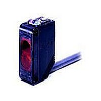
... Ordering Information Sensors Sensing method Appearance Narrow-beam reflective * The following table shows the model numbers of e-CON Pre-wired Connectors that are available. The Ratings and Specifications are the same as those for the E3Z-L61. Cable length Model 0.3 m E3Z-L61-ECON 0.3M 0.5 m E3Z-L61-ECON 0.5M ...
Page 2
... Distance (mm) http://www.ia.omron.com/ Narrow-beam reflective E3Z-L61 E3Z-L81 Load current 100 mA max times each in the X, Y, and Z directions Connector (M8, 4 pins) Approx Excess Gain vs. Sensing Distance 100 0.7 0.5 0.3 0.1 ...
Page 3
... Incident light No incident light Operation ON indicator OFF (orange) Light-ON ON Output transistor OFF Operate Load (e.g., relay) Reset (Between brown and black leads) E3Z-L61 E3Z-L66 Incident light No incident light Operation ON indicator OFF (orange) Dark-ON Output ON transistor OFF Operate Load (e.g., relay) Reset ...
Page 4
... This product is not designed or rated for ensuring safety of persons either directly or indirectly. Do not use it for such purposes. Precautions for Correct Use Do not use the product in atmospheres or environments that exceed product ratings. Dimensions Sensors Pre-wired Models E3Z-L61 Operation indicator (orange) E3Z-L81 10.8 10.4 Stability indicator Receiver 2.1 ...
Page 5
... Example: Incorrect Polarity Wiring Load - Brown Black Sensor + Blue • AC 2-wire Sensors Example: E3E2 etc. Brown 12 to 24VDC Sensor Black Sensor 0V Blue (c)Copyright OMRON Corporation 2007 All Rights Reserved. --- Load (Load short circuit) Brown Blue Load Load Brown Sensor Black Blue - Black + Brown Blue + ...
Page 6
... Performance, however, will depend on conditions. Refer to pages E3X-DA-S/E3X-MDA and E3C-LDA. E3X-NA Fiber Sensors E3T, E3Z, E3ZM, E3ZM-C, E3S-C, E3G-L1/L3, or E3S-C Built-in Amplifier Photoelectric Sensors (except Through-beam Sensors) E3C Photoelectric Sensor with separate amplifier If the workpieces move from far to near, chattering may occur in the vicinity of the operating point ...
Page 7
... N max. Work Required for Unconnected Leads Unused leads for self-diagnosis outputs or other special functions should be cut and wrapped with insulating tape to prevent contact with other terminals. on (c)Copyright OMRON Corporation 2007 All Rights Reserved. After countermeasure Insert an insulator. +V Inverter motor Sensor ...
Page 8
... Result The testing conditions of the standard cable and robot cable are different. Refer to the values in the above table to check bend-resistant performance under actual working conditions. (c)Copyright OMRON Corporation 2007 All Rights Reserved. (2) (1) (3) θ θ R Weight Robot cable: Strong, ...
Page 9
... Lock released position Emitter Protective cover Optical axis: Mechanical axis: The axis perpendicular to the center of the lens. Emitter Emission beam (c)Copyright OMRON Corporation 2007 All Rights Reserved. Receiver Incident indicator or Operation indicator ON OFF Optimum value ...
Page 10
... The lens and case of the Photoelectric Sensor are primarily made of plastic. Dirt should be gently wiped off with a dry cloth. Do not use thinner or other organic solvents. • The case of the E3ZM, E3ZM-C and E3S-C is metal. The lens, however, is plastic. ● Accessories Using a Reflector (E39-R3/R37/RS1/RS2/RS3) ...
Page 11
... Please read and understand this catalog before purchasing the products. Please consult your OMRON representative if you have any questions or comments. WARRANTY OMRON's exclusive warranty is that the products are free from defects in materials and workmanship for a period of one year (or other period if specifi ed) from date of sale by OMRON. OMRON MAKES NO WARRANTY OR REPRESENTATION, EXPRESS OR IMPLIED, REGARDING NON-INFRINGEMENT, MERCHANTABILITY, OR FITNESS FOR PARTICULAR PURPOSE OF THE PRODUCTS ...