G6B-4BND-DC24 Omron, G6B-4BND-DC24 Datasheet - Page 2
G6B-4BND-DC24
Manufacturer Part Number
G6B-4BND-DC24
Description
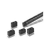
RELAY TERMINAL BLOCK -STD.
Manufacturer
Omron
Series
G6B-4r
Specifications of G6B-4BND-DC24
Relay Type
General Purpose
Contact Form
4PST (4 Form A)
Contact Rating (current)
5A
Switching Voltage
380VAC, 125VDC - Max
Coil Type
Standard
Coil Current
10.7mA
Coil Voltage
24VDC
Turn On Voltage (max)
19.2 VDC
Turn Off Voltage (min)
2.4 VDC
Mounting Type
DIN Rail
Termination Style
Screw Terminal
Circuit
4PST (4 Form A)
Contact Rating @ Voltage
5A @ 250VAC
Control On Voltage (max)
19.2 VDC
Control Off Voltage (min)
2.4 VDC
Contact Rating
5 A
Contact Termination
Through Hole
Mounting Style
PCB
Power Consumption
200 mW
Contact Material
Silver Alloy
Lead Free Status / RoHS Status
Lead free / RoHS Compliant
Lead Free Status / RoHS Status
Lead free / RoHS Compliant
Other names
G6B-4BND-DC24
G6B4BNDDC24
Z2983
G6B4BNDDC24
Z2983
Available stocks
Company
Part Number
Manufacturer
Quantity
Price
Company:

Part Number:
G6B-4BND-DC24V
Manufacturer:
OMRON
Quantity:
5 400


Specifications
■ Ratings
Coil Ratings (per G6B Relay)
Note: 1. Rated current and coil resistance were measured at a coil temperature of 23 C with a tolerance of 20%.
Contact Ratings
Note: This value fulfills the P reference value of opening/closing at a rate of 120 times per min (ambient operating environment and determination
■ Characteristics
Note: 1. The above values are initial values.
Rated voltage
Rated current
Coil resistance
Must operate voltage
Must release voltage
Max. voltage
Power consumption
Classification
Load
Rated load
Rated carry current
Max. switching voltage
Max. switching current
Max. switching power
Error rate (reference value) (see note) 10 mA at 5 VDC
Contact resistance (see note 2)
Operate time
Release time
Switching power
Insulation resistance
Dielectric strength
Vibration resistance
Shock resistance
Endurance
Ambient temperature
Ambient humidity
Weight
2. Operating characteristics were measured at a coil temperature of 23 C.
3. The maximum allowable voltage is the maximum value of the allowable voltage range for the relay coil operating power supply. There is
4. Diodes to absorb coil surge are equivalent to S5688J (reverse voltage resistance: 600 V; forward current: 1 A).
criteria according to JIS C5442).
2. Measurement condition: 1 A at 5 VDC
no continuous allowance.
G6B-4BND (standard), G6B-47BND (long-life)
Resistive load
(cos = 1)
5 A at 250 VAC,
5 A at 30 VDC
5 A
380 VAC, 125 VDC
5 A
1,250 VA, 150 W
5 VDC
35.5 mA
125
80% max. of rated voltage
10% min. of rated voltage
130% of rated voltage
Approx. 200 mW
100 m
10 ms max. (approx. 3 ms)
15 ms max. (approx. 4 ms)
Mechanical: 18,000 operations/hr
Rated load: 1,800 operations/hr
1,000 M
2,000 VAC, 50/60 Hz for 1 min between coil and contacts
2,000 VAC, 50/60 Hz for 1 min between contacts of different polarity
1,000 VAC, 50/60 Hz for 1 min between contacts of same polarity
250 VAC, 50/60 Hz for 1 min between coils of different polarity
Destruction: 10 to 55 to 10 Hz, 0.75-mm single amplitude (1.5-mm double amplitude)
Malfunction: 10 to 55 to 10 Hz, 0.75-mm single amplitude (1.5-mm double amplitude)
Destruction: 1,000 m/s
Malfunction: 100 m/s
Mechanical: 50,000,000 operations min. (at 18,000 operations/hr)
Electrical:
Operating: –25 C to 55 C (with no icing or condensation)
Storage:
Operating: 35% to 85%
Approx. 75 g
max.
min. (at 500 VDC)
–25 C to 55 C (with no icing or condensation)
100,000 operations min. (at 1,800 operations/hr, rated load)
500,000 operations min. for long-life at 2 A
100,000 operations min for long-life at 5 A
2
(approx. 10G)
2
(approx. 100G)
Inductive load
(cos = 0.4, L/R = 7 ms)
2 A at 250 VAC,
2 A at 30 VDC
500 VA, 60 W
12 VDC
19.1 mA
720
Terminal Relay
G6B-48BND (high-reliability)
Resistive load
(cos = 1)
2 A at 250 VAC,
2 A at 30 VDC
2 A
2 A
500 VA, 60 W
1 mA at 1 VDC
G6B-4@@ND
24 VDC
10.7 mA
2,880
Inductive load
(cos = 0.4, L/R = 7 ms)
0.5 A at 250 VAC,
0.5 A at 30 VDC
125 VA, 15 W
203
Related parts for G6B-4BND-DC24
Image
Part Number
Description
Manufacturer
Datasheet
Request
R

Part Number:
Description:
RELAY TERMINAL BLOCK -STD.
Manufacturer:
Omron
Datasheet:
Part Number:
Description:
RELAY TERMINAL BLOCK -STD.
Manufacturer:
Omron
Datasheet:

Part Number:
Description:
POWER RELAY, 4PST-NO, 24VDC, 5A DIN RAIL
Manufacturer:
Omron
Datasheet:
Part Number:
Description:
RELAY TERMINAL BLOCK
Manufacturer:
Omron
Datasheet:
Part Number:
Description:
RELAY TERMINAL BLOCK -L.L.
Manufacturer:
Omron
Datasheet:
Part Number:
Description:
RELAY TERMINAL BLOCK -L.L.
Manufacturer:
Omron
Datasheet:
Part Number:
Description:
RELAY TERMINAL BLOCK -H.R.
Manufacturer:
Omron
Datasheet:
Part Number:
Description:
RELAY TERMINAL BLOCK-STD.
Manufacturer:
Omron
Datasheet:
Part Number:
Description:
RELAY TERMINAL BLOCK -STD.
Manufacturer:
Omron
Datasheet:

Part Number:
Description:
POWER PCB RELAY
Manufacturer:
Omron
Datasheet:
Part Number:
Description:
POWER PCB RELAY
Manufacturer:
Omron
Datasheet:

Part Number:
Description:
RELAY PWR DPST-NC PCB
Manufacturer:
Omron
Datasheet:
Part Number:
Description:
POWER PCB RELAY
Manufacturer:
Omron
Datasheet:
Part Number:
Description:
POWER PCB RELAY
Manufacturer:
Omron
Datasheet:

Part Number:
Description:
PCB G6B SOCKET
Manufacturer:
Omron
Datasheet: