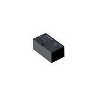
G6Y-1-DC24 Omron, G6Y-1-DC24 Datasheet - Page 3

G6Y-1-DC24
Manufacturer Part Number
G6Y-1-DC24
Description
LOW SIGNAL RF RELAY
Manufacturer
Omron
Series
G6Yr
Datasheet
1.G6Y-1-DC5.pdf
(6 pages)
Specifications of G6Y-1-DC24
Contact Form
1 Form C
Coil Voltage
24 VDC
Coil Current
8.3 mA
Coil Type
Non-Latching
Power Consumption
200 mW
Termination Style
Solder Pin
Isolation
65 dB at 900 MHz
Insertion Loss
0.5 dB at 900 MHz
Maximum Switching Current
500 mA
Contact Rating
0.01 A at 30 VAC / 30 VDC
Lead Free Status / RoHS Status
Lead free / RoHS Compliant
Lead Free Status / RoHS Status
Lead free / RoHS Compliant
Other names
G6Y124DC OMRG6Y124DC
Available stocks
Company
Part Number
Manufacturer
Quantity
Price
Company:
Part Number:
G6Y-1-DC24V
Manufacturer:
OMRON
Quantity:
12 000
■ High-frequency Characteristics
Measurement Conditions
Note: 1. The tests were conducted at an ambient temperature of 23°C.
Dimensions
Note: All units are in millimeters unless otherwise indicated.
G6Y-1
■ Isolation,
100
30
40
50
60
70
80
90
■ Operating/Release Time
50
40
30
20
10
(See notes 1 and 2.)
Average Values
0
HP 8753D
Network
Analyser
0
Distribution (See note 1.)
2. High-frequency characteristics depend on the PCB to which the Relay is mounted. Always check these characteristics, including
1
endurance (life expectancy), in the actual machine before use.
500
Sample: G6Y-1
Quantity: 50 Units
2
1,000
3
4
1,500
Frequency (MHz)
20.7 max.
(20.5)*
15.24
5
* Average value
2,000
6
Time (ms)
OUT
OUT
Operating
Release
time
time
IN
7
2,500
(2.05)
11.7 max.
(11.5)*
8
14 (8)
8 (14)
7.62
11
G6Y-1
■ Insertion Loss,
0.1
0.2
0.3
0.4
0.5
0.6
0.7
0.8
0.9
■ Bounce Time Distribution
0
1
(9.0)*
Average Values
(See notes 1 and 2.)
9.2 max.
50
40
10
30
20
(See note 1.)
0
0
3
(Holes for the coil terminals may also be 1.0.)
Subject: G6Y-1
Quantity: 50 Units
1
(2.63)
500
50-Ω
Terminator
Tolerances: ±0.1 mm.
PCB Dimensions
(Bottom View)
2
1,000
Terminals which were not being measured were terminated with 50 Ω.
Note: The high-frequency characteristics data were measured using
3
Six, 1.2-dia. holes
4
1,500
Frequency (MHz)
a dedicated circuit board and actual values will vary depending
on the usage conditions. Check the characteristics of the actual
equipment being used.
5
Operating bounce time
Release bounce time
2,000
Three, 0.8-dia. holes
6
Time (ms)
(2.63)
(2.05)
7
(1.83)
2,500
High Frequency Relay
8
Note: The shaded and unshaded parts
10
20
30
40
50
60
■ V.S.W.R. / Return Loss,
0
0
(See notes 1 and 2.)
Average Values
indicate the product's directional marks.
(There is no polarity to the coil.)
Return loss
500
Terminal Arrangement/
Internal Connections
(Bottom View)
1,000
1,500
Frequency (MHz)
G6Y
V.S.W.R.
2,000
2,500
337
2.2
2
1.8
1.6
1.4
1.2
1


