P7SA-10F Omron, P7SA-10F Datasheet
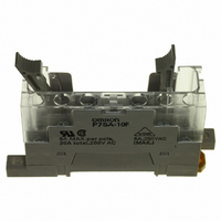
Contact OSTI For Purchase

P7SA-10F

Manufacturer Part Number
P7SA-10F
Description
Contact OSTI For Purchase
Manufacturer
Omron
Series
G7SAr
Type
Socketr
Datasheets

Specifications of P7SA-10F

Number Of Positions
10
Mounting Type
DIN Rail
Termination Style
Screw Terminal
Associated Relay Series
G7SA
Number Of Poles
4
Accessory Type
Sockets
Lead Free Status / RoHS Status
Lead free / RoHS Compliant
For Use With/related Products
G7SA Series
For Use With
Z2943 - RELAY SAFETY PCB 3PST-NO/1NC 24V
Lead Free Status / Rohs Status
Lead free / RoHS Compliant
Other names
P7SA10F
Z2947

Available stocks

Company
Part Number
Manufacturer
Quantity
Price
Part Number:
P7SA-10F
Manufacturer:
Omron Electronics Inc-EMC Div
Quantity:
135
■ Approved Standards
G7SA
• EN Standards, VDE Approved
■ Ratings
Coil
Note: 1. The rated current and coil resistance are measured at a coil temperature of 23 C with tolerances of 15%.
Compact, Slim Relays Conforming to EN
Standards
• Relays with forcibly guided contacts (EN50205 Class A,
• Supports the CE marking of machinery (Machinery Directive).
• Helps avoid hazardous machine status when used as part of an
• Four-pole and six-pole Relays are available.
• The Relay’s terminal arrangement simplifies PWB pattern design.
• Reinforced insulation between inputs and outputs.
Ordering Information
Relays with Forcibly Guided Contacts
Sockets
Model Number Structure
■ Model Number Legend
G7SA-@A@B
Rated voltage
24 VDC
Standard
Track-mounting
Back-mounting
EN61810-1 (Electromechanical non-specified time all-or-nothing relays)
EN50205 (Relays with forcibly guided (linked) contacts)
approved by VDE).
interlocking circuit.
Relays with Forcibly Guided Contacts
G7SA
2. Performance characteristics are based on a coil temperature of 23 C.
3. The value given for the maximum voltage is for voltages applied instantaneously to the Relay coil (at an ambient temperature of 23 C)
and not continuously.
Type
1
4 poles: 15 mA
6 poles: 20.8 mA
2
Rated current
Track mounting and screw mounting possible
PCB terminals
Flux-tight
1. NO Contact Poles
2: DPST-NO
3: 3PST-NO
4: 4PST-NO
5: 5PST-NO
Sealing
Type
4 poles: 1,600
6 poles: 1,152
Coil resistance
4 poles
6 poles
2. NC Contact Poles
Poles
75% max. (V)
1: SPST-NC
2: DPST-NC
3: 3PST-NC
Reinforced insulation between some poles of different polarity.
Must-operate
voltage
Relays with Forcibly Guided Contacts
No
Yes
No
3PST-NO, SPST-NC
DPST-NO, DPST-NC
5PST-NO, SPST-NC
4PST-NO, DPST-NC
3PST-NO, 3PST-NC
LED indicator
• UL standard UL508 Industrial Control Devices
• CSA standard CSA C22.2 No. 14 Industrial Control Devices
10% min. (V)
Contacts
Must-release
voltage
4 poles
6 poles
4 poles
6 poles
4 poles
6 poles
24 VDC
Poles
110% (V)
Max. voltage
Rated voltage
---
---
24 VDC
Rated voltage
4 poles: Approx. 360 mW
6 poles: Approx. 500 mW
Power consumption
G7SA
G7SA-3A1B
G7SA-2A2B
G7SA-5A1B
G7SA-4A2B
G7SA-3A3B
P7SA-10F
P7SA-14F
P7SA-10F-ND
P7SA-14F-ND
P7SA-10P
P7SA-14P
Model
Model
G-3

Related parts for P7SA-10F

P7SA-10F Summary of contents

Page 1

... Rated voltage Model 24 VDC G7SA-3A1B G7SA-2A2B G7SA-5A1B G7SA-4A2B G7SA-3A3B Poles Rated voltage Model 4 poles --- P7SA-10F 6 poles P7SA-14F 4 poles 24 VDC P7SA-10F-ND 6 poles P7SA-14F-ND 4 poles --- P7SA-10P 6 poles P7SA-14P Max. voltage Power consumption 110% (V) 4 poles: Approx. 360 mW 6 poles: Approx. 500 mW G7SA G-3 ...

Page 2

... P7SA-14 (See note 1.) Note the P7SA-1@F is used between 55 and 85 C, reduce the continuous current (from 0.1 A for every degree. 2. Measurement conditions: Measurement of the same points as for the dielectric strength at 500 VDC. 3. When using the P7SA-1@F- VDC, use at an ambient operating temperature from ...

Page 3

Dimensions Note: All units are in millimeters unless otherwise indicated. The diagrams are drawn in perspective. ■ Relays with Forcibly Guided Contacts G7SA-3A1B G7SA-2A2B 40 max. 0.5 G7SA-5A1B G7SA-4A2B G7SA-3A3B 50 max. G-6 Relays with Forcibly Guided Contacts Terminal Arrangement/ ...

Page 4

... Sockets Track-mounting Socket P7SA-10F, P7SA-10F-ND 22.5 max. Ten max. 72 max. LED indicator 9 max. 4 dia. Note: The socket is shown with the finger cover removed. Note: Only the -ND Sockets have LED indicators (orange) Track-mounting Socket P7SA-14F, P7SA-14F-ND 30 max. Fourteen max. 72 max. LED indicator 9 max ...

Page 5

... P7SA-10P Back-mounting Socket (for PCB) 50 max. P7SA-14P Back-mounting Socket (for PCB) 60 max. 15 max. 41.5 max. Three, 2.6 dia. (for M3 tapping screws) G-8 Relays with Forcibly Guided Contacts Terminal Arrangement/Internal Connection Diagram 15 max. (Bottom View) G7SA-3A1B Mounted 41.5 max. G7SA-2A2B Mounted Three, 2.6 dia. ...

Page 6

... Precautions for Correct Use !CAUTION Do not touch the terminal area of the Relays or the socket terminal area (charged area) while power is ON. Electric shock will result. Wiring Use one of the following wires to connect to the P7SA-10F/10F-ND/ 14F/14F-ND. 2 Stranded wire: 0. Solid wire: 1 ...

Page 7

... Cancellation; Etc. Orders are not subject to rescheduling or cancellation unless Buyer indemnifies Omron against all related costs or expenses. 10. Force Majeure. Omron shall not be liable for any delay or failure in delivery resulting from causes beyond its control, including earthquakes, fires, floods, strikes or other labor disputes, shortage of labor or materials, accidents to machinery, acts of sabotage, riots, delay in or lack of transportation or the requirements of any government authority ...

Page 8

Cat. No. GC SAFETY-3A 07/05-11/06 Specifications subject to change without notice Printed in USA ...

Related keywords