P9EA-C Omron, P9EA-C Datasheet

TERMINAL COVER FOR G9EA

P9EA-C

Manufacturer Part Number
P9EA-C
Description
TERMINAL COVER FOR G9EA
Manufacturer
Omron
Series
G9EA-1r
Datasheet

Specifications of P9EA-C

Accessory Type
Cover, Terminal
Associated Relay Series
G9EA-1
Width
36 mm
Rohs Compliant
Yes
Lead Free Status / RoHS Status
Lead free / RoHS Compliant
For Use With/related Products
G9EA-1 Series
For Use With
G9EA-1DC60 - RELAY DC IND SPST 60VDCG9EA-1DC48 - RELAY DC IND SPST 48VDCG9EA-1DC100 - RELAY DC IND SPST 100VDCG9EA-1-CADC48 - RELAY DC IND SPST 48VDCG9EA-1-CADC100 - RELAY DC IND SPST 100VDCG9EA-1-BDC60 - RELAY DC IND SPST 60VDCG9EA-1-BDC48 - RELAY DC IND SPST 48VDCG9EA-1-BDC100 - RELAY DC IND SPST 100VDCG9EA-1-B-CADC60 - RELAY DC IND SPST 60VDCG9EA-1-B-CADC48 - RELAY DC IND SPST 48VDCG9EA-1-B-CADC100 - RELAY DC IND SPST 100VDCZ1617 - RELAY IND SPST 100ADC SCREW TERMZ1616 - RELAY IND SPST 100ADC SCREW TERMZ1615 - RELAY IND SPST 100ADC LEAD TERMZ1614 - RELAY IND SPST 100ADC LEAD TERMZ1613 - RELAY IND SPST 60ADC LEAD TERMZ1612 - RELAY IND SPST 60ADC LEAD TERMZ1611 - RELAY IND SPST 60ADC SCREW TERMZ1610 - RELAY IND SPST 60ADC SCREW TERM
Color
-
Lead Free Status / Rohs Status
Lead free / RoHS Compliant
Other names
P9EAC
DC Power Relays Capable of Interrupting
High-voltage, High-current Loads
• A compact relay (73 x 36 x 67.2 mm (L x W x H)) capable of
• The switching section and driving section are gas-injected and
• Downsizing and optimum design allow no restrictions on the
• Terminal Cover and DIN Track Adapters are also available for in-
• UL/CSA standard UL508 approved.
Note: Refer to Precautions on page 22.
Model Number Structure
■ Model Number Legend
1. Number of Poles
2. Contact Form
3. Coil Terminals
4. Special Functions
Ordering Information
■ List of Models
Note: 1. Two M5 screws are provided for the contact terminal connection.
G9EA-@-@-@-@
Switching/current con-
duction models
High-current conduc-
tion models
switching 400-V 60-A DC loads. (Capable of interrupting 600 A
at 300 VDC max.)
hermetically sealed, allowing these compact relays to interrupt
high-capacity loads. The sealed construction also requires no
arc space, saves space, and helps ensure safe applications.
mounting direction.
dustrial applications.
DC Power Relays (60-A, 100-A Models)
G9EA-1
1:
Blank: SPST-NO
B:
Blank: Lead wire output
CA:
2. Two M3.5 screws are provided for the coil terminal connection.
Models
1 pole
M3.5 screw terminals
High-current conduction (100 A)
1
2
3 4
Screw terminals (See note 2.)
Lead wires
Screw terminals (See note 2.)
Lead wires
Coil terminals
Terminals
Screw terminals
(See note 1.)
Contact terminals
DC Power Relays (60-A, 100-A Models)
SPST-NO
Contact form
12 VDC
24 VDC
48 VDC
60 VDC
100 VDC
Rated coil voltage
G9EA-1
G9EA-1-B
G9EA-1
G9EA-1-B-CA
G9EA-1-CA
Model
5

Related parts for P9EA-C

P9EA-C Summary of contents

Page 1

DC Power Relays (60-A, 100-A Models) G9EA-1 DC Power Relays Capable of Interrupting High-voltage, High-current Loads • A compact relay ( 67 H)) capable of switching 400-V 60-A DC loads. (Capable of ...

Page 2

Specifications ■ Ratings Coil Rated voltage Rated current Coil resistance 28.8 Ω 12 VDC 417 mA 115.2 Ω 24 VDC 208 mA 469.3 Ω 48 VDC 102 mA 695.7 Ω 60 VDC 86.2 mA 1,864 Ω 100 VDC 53.6 mA ...

Page 3

Engineering Data ■ G9EA-1(-B) Switching/Current Conduction Models Maximum Switching Capacity 1,000 500 300 G9EA-1 DC resistive load 100 100 300 500 1,000 Switching voltage (V) Carry Current vs Energizing Time 100,000 ...

Page 4

All G9EA-1 Models Must-operate Voltage and Must-release Voltage Distributions 30 Must-operate voltage Sample: G9EA-1 Number: 35 Must-release voltage 100 Percentage of rated voltage (%) Vibration Resistance 10.0 Sample: G9EA-1 ...

Page 5

Dimensions Note: All units are in millimeters unless otherwise indicated. Models with Screw Terminals G9EA-1-B(-CA ...

Page 6

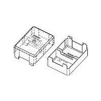
... Options Terminal Cover P9EA-C DIN Track Adapter P9EA Power Relays (60-A, 100-A Models) 17* 31 13. 17* 17 Dimensions of cutouts for wiring. Two, M5 61± 88 0.1 24± 0 G9EA-1 Note: Be sure to remove the cutouts for wiring that are located in 36 the wiring outlet direction be- fore installing the Terminal Cover ...

Page 7

Precautions WARNING Take measures to prevent contact with charged parts when using the Relay for high voltages. ■ Precautions for Correct Use Refer to the relevant catalog for common precautions sure to tighten all screws to the appropriate ...

Related keywords