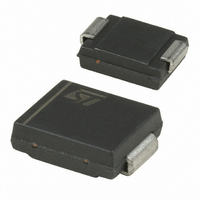
STTH3R02S STMicroelectronics, STTH3R02S Datasheet - Page 5

STTH3R02S
Manufacturer Part Number
STTH3R02S
Description
DIODE ULT FAST 1200V 3A SMC
Manufacturer
STMicroelectronics
Datasheet
1.STTH3R02QRL.pdf
(9 pages)
Specifications of STTH3R02S
Voltage - Forward (vf) (max) @ If
1V @ 3A
Voltage - Dc Reverse (vr) (max)
200V
Current - Average Rectified (io)
3A
Current - Reverse Leakage @ Vr
3µA @ 200V
Diode Type
Standard
Speed
Fast Recovery =< 500ns, > 200mA (Io)
Reverse Recovery Time (trr)
30ns
Mounting Type
Surface Mount
Package / Case
DO-214AB, SMC
Product
Ultra Fast Recovery Rectifier
Configuration
Single
Reverse Voltage
200 V
Forward Voltage Drop
1.2 V at 9 A
Recovery Time
30 ns
Forward Continuous Current
3 A
Max Surge Current
75 A
Reverse Current Ir
3 uA
Mounting Style
SMD/SMT
Maximum Operating Temperature
+ 175 C
Minimum Operating Temperature
- 65 C
Lead Free Status / RoHS Status
Lead free / RoHS Compliant
Capacitance @ Vr, F
-
Lead Free Status / Rohs Status
Lead free / RoHS Compliant
Other names
497-6085-2
Available stocks
Company
Part Number
Manufacturer
Quantity
Price
Company:
Part Number:
STTH3R02S
Manufacturer:
ST
Quantity:
214 000
Company:
Part Number:
STTH3R02S
Manufacturer:
STMicroelectronics
Quantity:
3 090
Part Number:
STTH3R02S
Manufacturer:
VISHAY/威世
Quantity:
20 000
STTH3R02
2
Figure 11. Dynamic parameters versus
Figure 13. Thermal resistance versus copper
100
1.4
1.2
1.0
0.8
0.6
0.4
0.2
0.0
80
60
40
20
0
25
0.0
V
R
I
F
=160V
0.5
=3A
Ordering information scheme
junction temperature
surface under each lead for SMC
(Epoxy printed circuit board FR4,
e
50
1.0
CU
= 35µm)
I
RM
1.5
Q
RR
75
2.0
S
CU
(cm²)
2.5
100
3.0
Ultrafast switching diode
Average forward current
3 = 3 A
02 = 200 V
Blank = DO-201 in Ammopack
RL = DO-201 in Tape and reel
Q = DO-15 in Ammopack
QRL = DO-15 in Tape and reel
S= SMC in Tape and reel
Model R
Repetitive peak reverse voltage
Package
3.5
125
4.0
T
j
(°C)
4.5
SMC
150
5.0
STTH
Figure 12. Thermal resistance junction to
Figure 14. Thermal resistance versus lead
100
100
90
80
70
60
50
40
30
20
10
90
80
70
60
50
40
30
20
10
3 R
0
0
0.0
5
0.5
02 XXX
ambient versus copper surface
under each lead for DO-15 and
DO-201AD (Epoxy printed circuit
board FR4, e
length for DO-201AD package
1.0
10
1.5
Ordering information scheme
2.0
R
R
th(j-a)
2.5
15
th(j-l)
CU
= 35µm)
3.0
3.5
20
4.0
L
leads
S
Cu
DO-201AD
(cm²)
DO-201AD
(mm)
DO-15
4.5
5.0
25
5/9


