R99-04 FOR G5F Omron, R99-04 FOR G5F Datasheet - Page 9
R99-04 FOR G5F
Manufacturer Part Number
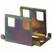
R99-04 FOR G5F
Description
MOUNTING BRACKET -G7J
Manufacturer
Omron
Series
G7Jr
Specifications of R99-04 FOR G5F
Accessory Type
Mounting Bracket, Plate
Associated Relay Series
G7J
Termination Style
Screw
Mounting Style
Screw
Width
28 mm
Lead Free Status / RoHS Status
Lead free / RoHS Compliant
For Use With/related Products
G7J Series
For Use With
G7J-4A-TDC6 - RELAY GP PWR 4PST QC TERMG7J-4A-TDC48 - RELAY GP PWR 4PST QC TERMG7J-4A-TDC24 - RELAY GP PWR 4PST QC TERMG7J-4A-TDC12 - RELAY GP PWR 4PST QC TERMG7J-4A-TDC100 - RELAY GP PWR 4PST QC TERMG7J-4A-TAC24 - RELAY GP PWR 4PST QC TERMG7J-4A-TAC200/240 - RELAY GP PWR 4PST QC TERMG7J-4A-TAC100/120 - RELAY GP PWR 4PST QC TERMG7J-4A-BDC48 - RELAY GP PWR 4PST SCREW TERMG7J-3A1B-TDC6 - RELAY GP PWR 3PST-NO/1NC QCG7J-3A1B-TDC48 - RELAY GP PWR 3PST-NO/1NC QCG7J-3A1B-TDC12 - RELAY GP PWR 3PST-NO/1NC QCG7J-3A1B-TDC100 - RELAY GP PWR 3PST-NO/1NC QCG7J-3A1B-TAC50 - RELAY GP PWR 3PST-NO/1NC QCG7J-3A1B-TAC24 - RELAY GP PWR 3PST-NO/1NC QCG7J-3A1B-TAC200/240 - RELAY GP PWR 3PST-NO/1NC QCG7J-3A1B-TAC100/120 - RELAY GP PWR 3PST-NO/1NC QCG7J-3A1B-BDC12 - RELAY PWR 3PST-NO/1NC 25AG7J-3A1B-BAC24 - RELAY PWR 3PST-NO/1NC 25AG7J-2A2B-TDC6 - RELAY GP PWR DPST-NO/NC QC TERMG7J-2A2B-TDC48 - RELAY GP PWR DPST-NO/NC QC TERMG7J-2A2B-TDC24 - RELAY GP PWR DPST-NO/NC QC TERMG7J-2A2B-TDC12 - RELAY GP PWR DPST-NO/NC QC TERMG7J-2A2B-TDC100 - RELAY GP PWR DPST-NO/NC QC TERMG7J-2A2B-TAC50 - RELAY GP PWR DPST-NO/NC QC TERMG7J-2A2B-TAC24 - RELAY GP PWR DPST-NO/NC QC TERMG7J-2A2B-TAC200/240 - RELAY GP PWR DPST-NO/NC QC TERMG7J-2A2B-TAC100/120 - RELAY GP PWR DPST-NO/NC QC TERMG7J-2A2B-BDC12 - RELAY PWR DPST-NO/NC 25AG7J-2A2B-BDC110 - RELAY PWR DPST-NO/NC 25AG7J-2A2B-BDC100 - RELAY PWR DPST-NO/NC 25AG7J-2A2B-BAC50 - RELAY PWR DPST-NO/NC 25AG7J-4A-B-DC24 - RELAY PWR 4PST 25A 24VDCG7J-4A-B-DC12 - RELAY PWR 4PST 25A 12VDCG7J-4A-B-AC24 - RELAY PWR 4PST 25A 24VACG7J-4A-BAC200/240 - RELAY PWR 4PST 25A 230VACG7J-4A-BAC100/120 - RELAY PWR 4PST 25A 120VACG7J-3A1B-B-DC24 - RELAY PWR 3PST-NO/1NC 25A 24VDCG7J3A1BBAC200/240 - RELAY PWR 3PST-NO/1NC 25A 230VACG7J3A1BBAC100/120 - RELAY PWR 3PST-NO/1NC 25A 120VACG7J-2A2B-B-DC48 - RELAY PWR DPST-NO/NC 25A 48VDCG7J-2A2B-B-DC24 - RELAY PWR DPST-NO/NC 25A 24VACG7J-2A2B-B-AC24 - RELAY PWR DPST-NO/NC 25A 24VACG7J2A2BBAC200/240 - RELAY PWR DPST-NO/NC 25A 230VACG7J2A2BBAC100/120 - RELAY PWR DPST-NO/NC 25A 120VAC
Color
-
Lead Free Status / Rohs Status
Lead free / RoHS Compliant
Other names
R99-04
R99-04
R99-04FORG5F
R9904
R9904FORG5F
Z1238
R99-04
R99-04FORG5F
R9904
R9904FORG5F
Z1238


Safety Precautions
Refer to Safety Precautions for All Relays.
■ Correct Use
Installation
PCB Terminal-equipped Relays weigh approximately 140 g. Be sure that
the PCB is strong enough to support them. We recommend dual-side
through-hole PCBs to reduce solder cracking from heat stress.
Mount the G7J with its test button facing downwards. The Relay may
malfunction due to shock if the test button faces upwards. Be careful
not to press the test button by mistake because the contacts will go
ON if the test button is pressed.
If the normal mounting direction is not used, carbides or powder from
contact abrasion that results from load switching will accumulate
inside the Relay. If the Relay is used past its endurance in this state,
insulation failure between circuits of different polarity or Relay burn-
ing may occur.
Be sure to use the test button for test purposes only.
The test button is used for Relay circuit tests, such as a circuit conti-
nuity test. Do not attempt to switch the load with the test button.
If a voltage is applied to the coil, the test button will retract in an ON
state (i.e., an excited state).
Micro Loads
The G7J is used for switching power loads, such as motor, trans-
former, solenoid, lamp, and heater loads. Do not use the G7J for
switching minute loads, such as signals. Use a Relay with a bifur-
cated contact construction for switching micro loads, in which case,
however, only SPST-NO or SPST-NC output is obtained.
Soldering PCB Terminals
Be sure to solder the PCB terminals manually only. In the case of
automatic soldering, some flux may stick to the test button and the
G7J. As a result, the G7J may malfunction.
The G7J is not of enclosed construction. Therefore, do not wash the
G7J with water or any detergent.
Connecting
Refer to the following diagram when connecting a wire with a screw
terminal to the G7J.
Allow suitable slack on leads when wiring, and do not subject the ter-
minals to excessive force.
Tighter the terminal screws with torque 0.78 to 1.18 N·m. Loose
screws result in disconnection of lead wire, malfunction or fire.
4.5
7
ALL DIMENSIONS SHOWN ARE IN MILLIMETERS.
To convert millimeters into inches, multiply by 0.03937. To convert grams into ounces, multiply by 0.03527.
7.6
In the interest of product improvement, specifications are subject to change without notice.
M3.5
8.8
Faston Tabs
Do not impose excessive external force on the G7J in the horizontal
or vertical directions when inserting the G7J to the Faston receptacle
or pulling the G7J out from the Faston receptacle. Do not attempt to
insert or pull out more than one G7J Unit together.
Do not solder the tab terminals.
Note: Numbers in parentheses are for air feed use.
Operating Coil
Internal Connections of Coils
If a transistor drives the G7J, check the leakage current, and connect
a bleeder resistor if necessary.
The AC coil is provided with a built-in full-wave rectifier. If a triac,
such as an SSR, drives the G7J, the G7J may not release. Use the
Power MOS FET Relay in this case.
#250 terminal
(6.35 mm in
width)
Terminal
AMP170333-1
(170327-1)
AMP170334-1
(170328-1)
AMP170335-1
(170329-1)
A2
A2
Receptacle
DC coil
AC coil
AMP172076-1: natural
AMP172076-4: yellow
AMP172076-5: green
AMP172076-6: blue
A1
A1
Housing
G7J
9
Related parts for R99-04 FOR G5F
Image
Part Number
Description
Manufacturer
Datasheet
Request
R

Part Number:
Description:
Mounting Bracket
Manufacturer:
Omron
Datasheet:

Part Number:
Description:
G6S-2GLow Signal Relay
Manufacturer:
Omron Corporation
Datasheet:
Part Number:
Description:
Compact, Low-cost, SSR Switching 5 to 20 A
Manufacturer:
Omron Corporation
Datasheet:
Part Number:
Description:
Manufacturer:
Omron Corporation
Datasheet:
Part Number:
Description:
Manufacturer:
Omron Corporation
Datasheet:
Part Number:
Description:
Manufacturer:
Omron Corporation
Datasheet:
Part Number:
Description:
Manufacturer:
Omron Corporation
Datasheet:
Part Number:
Description:
Manufacturer:
Omron Corporation
Datasheet:
Part Number:
Description:
Manufacturer:
Omron Corporation
Datasheet: