DSEP30-06B IXYS, DSEP30-06B Datasheet - Page 3
DSEP30-06B
Manufacturer Part Number
DSEP30-06B
Description
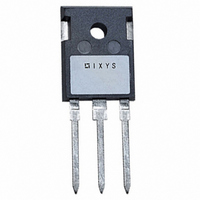
DIODE FRED 600V 30A TO-247AD
Manufacturer
IXYS
Series
HiPerFRED™r
Datasheet
1.DSEP30-06BR.pdf
(3 pages)
Specifications of DSEP30-06B
Voltage - Forward (vf) (max) @ If
2.51V @ 30A
Voltage - Dc Reverse (vr) (max)
600V
Current - Average Rectified (io)
30A
Current - Reverse Leakage @ Vr
250µA @ 600V
Diode Type
Standard
Speed
Fast Recovery =< 500ns, > 200mA (Io)
Reverse Recovery Time (trr)
30ns
Mounting Type
Through Hole
Package / Case
TO-247AD
Vrrm, (v)
600
Ifavm, D = 0.5, Total, (a)
30
Ifavm, D = 0.5, Per Diode, (a)
30
@ Tc, (°c)
125
Ifrms, (a)
70
Ifsm, 10 Ms, Tvj=45°c, (a)
250
Vf, Max, Tvj =150°c, (v)
1.56
@ If, (a)
30
Trr, Typ, Tvj =25°c, (ns)
30
Irm , Typ, Tvj =100°c, (a)
4.0
@ -di/dt, (a/µs)
100
Tvjm, (°c)
175
Rthjc, Max, (k/w)
0.90
Package Style
TO-247AC
Lead Free Status / RoHS Status
Lead free / RoHS Compliant
Capacitance @ Vr, F
-
Available stocks
Company
Part Number
Manufacturer
Quantity
Price
Company:

Part Number:
DSEP30-06B
Manufacturer:
IXYS
Quantity:
12 500
Part Number:
DSEP30-06B
Manufacturer:
IXYS/艾赛斯
Quantity:
20 000


Fig. 1 Forward current I
Fig. 4 Dynamic parameters Q
Fig. 7 Transient thermal resistance junction to case
IXYS reserves the right to change limits, test conditions and dimensions.
© 2004 IXYS All rights reserved
Z
I
0.001
F
K
thJC
0.01
100
K/W
f
2.0
1.5
1.0
0.5
0.0
0.1
0.00001
80
60
40
20
10
A
0
1
0
0
versus T
T
VJ
T
= 100°C
VJ
40
1
= 150°C
I
RM
Q
VJ
r
0.0001
80
2
T
F
T
VJ
VJ
versus V
V
120
= 25°C
F
3
V
r
C
, I
0.001
RM
160
F
4
t
rr
Q
140
120
100
300
250
r
200
150
100
Fig. 2 Reverse recovery charge Q
Fig. 5 Recovery time t
nC
80
60
40
50
ns
0
100
0.01
0
T
V
I
I
I
VJ
R
F
F
F
versus -di
200
= 60 A
= 30 A
= 15 A
= 300 V
= 100°C
T
V
VJ
R
= 300 V
= 100°C
400
F
0.1
/dt
-di
600
F
DSEP 30-06BR
-di
DSEP 30-06B
/dt
I
I
I
rr
F
F
F
t
F
/dt
= 60 A
= 30 A
= 15 A
versus -di
A/µs
s
800
A/µs
1000
1000
1
DSEP 30-06BR DSEP 30-06B
F
r
/dt
I
V
RM
FR
12
10
60
50
40
30
20
10
A
8
6
4
2
0
V
0
Fig. 3 Peak reverse current I
Constants for Z
Constants for Z
NOTE: Fig. 2 to Fig. 6 shows typical values
Fig. 6 Peak forward voltage V
0
0
T
I
1
2
3
1
2
3
4
V
F
i
i
VJ
FR
= 30 A
= 100°C
200
200
versus -di
versus di
I
I
I
F
F
F
400
400
= 60 A
= 30 A
= 15 A
R
0.465
0.179
0.256
R
0.368
0.1417
0.0295
0.5604
thi
thi
thJC
thJC
(K/W)
(K/W)
F
600
600
/dt
F
/dt
di
-di
calculation ..B:
calculation ..BR:
T
V
F
VJ
R
F
/dt
/dt
= 300 V
= 100°C
A/µs
A/µs
800
800 1000
t
0.0052
0.0003
0.0397
t
0.0052
0.0003
0.0004
0.0092
i
i
1000
t
(s)
(s)
fr
RM
FR
0.30
0.25
0.20
0.15
0.10
0.05
0.00
µs
and t
t
fr
3 - 3
fr
Related parts for DSEP30-06B
Image
Part Number
Description
Manufacturer
Datasheet
Request
R

Part Number:
Description:
DIODE 600V 30A ISOPLUS247
Manufacturer:
IXYS
Datasheet:

Part Number:
Description:
DIODE FRED 600V 30A TO-247AD
Manufacturer:
IXYS
Datasheet:

Part Number:
Description:
DIODE FRED 1200V 30A TO-247AD
Manufacturer:
IXYS
Datasheet:
Part Number:
Description:
DIODE FRED 1200V 30A ISOPLUS247
Manufacturer:
IXYS
Datasheet:
Part Number:
Description:
DIODE FRED 1200V 30A ISOPLUS247
Manufacturer:
IXYS
Datasheet:

Part Number:
Description:
DIODE HFRED 300V 30A TO-247AC
Manufacturer:
IXYS
Datasheet:

Part Number:
Description:
DIODE FRED 400V 30A TO-247AD
Manufacturer:
IXYS
Datasheet:
Part Number:
Description:
DIODE FRED 600V 30A ISOPLUS247
Manufacturer:
IXYS
Datasheet:
Part Number:
Description:
DIODE FRED 300V 30A TO-247AD
Manufacturer:
IXYS
Datasheet:

Part Number:
Description:
HiPerFREDTM Epitaxial Diode with soft recovery
Manufacturer:
IXYS Corporation
Part Number:
Description:
HiPerFET Power MOSFETs
Manufacturer:
IXYS Corporation
Datasheet: