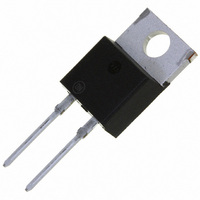
MBR1645G ON Semiconductor, MBR1645G Datasheet - Page 4

MBR1645G
Manufacturer Part Number
MBR1645G
Description
DIODE SCHOTTKY 45V 16A TO220AC
Manufacturer
ON Semiconductor
Series
SWITCHMODE™r
Specifications of MBR1645G
Voltage - Forward (vf) (max) @ If
630mV @ 16A
Voltage - Dc Reverse (vr) (max)
45V
Current - Average Rectified (io)
16A
Current - Reverse Leakage @ Vr
200µA @ 45V
Diode Type
Schottky
Speed
Fast Recovery =< 500ns, > 200mA (Io)
Mounting Type
Through Hole
Package / Case
TO-220-2, TO-220AC
Rectifier Type
Schottky Diode
Configuration
Single
Peak Rep Rev Volt
45V
Avg. Forward Curr (max)
16
Rev Curr
200uA
Peak Non-repetitive Surge Current (max)
150A
Forward Voltage
0.63V
Operating Temp Range
-65C to 175C
Package Type
TO-220AC
Operating Temperature Classification
Military
Mounting
Through Hole
Pin Count
2 +Tab
Product
Schottky Diodes
Peak Reverse Voltage
45 V
Forward Continuous Current
16 A
Max Surge Current
150 A
Forward Voltage Drop
0.63 V
Maximum Reverse Leakage Current
200 uA
Operating Temperature Range
- 65 C to + 175 C
Mounting Style
Through Hole
Current, Forward
16 A
Current, Reverse
40 mA
Current, Surge
150 A
Primary Type
Schottky Barrier
Resistance, Thermal, Junction To Case
1.5 °C/W
Temperature, Junction, Maximum
+175 °C
Temperature, Operating
-65 to +175 °C
Voltage, Forward
0.63 V
Voltage, Reverse
45 V
Lead Free Status / RoHS Status
Lead free / RoHS Compliant
Reverse Recovery Time (trr)
-
Capacitance @ Vr, F
-
Lead Free Status / Rohs Status
Compliant
Other names
MBR1645GOS
Available stocks
Company
Part Number
Manufacturer
Quantity
Price
Company:
Part Number:
MBR1645G
Manufacturer:
ON
Quantity:
12 500
Part Number:
MBR1645G
Manufacturer:
ON/安森美
Quantity:
20 000
VARIABLE
CONFIGURATION
ZONE
M
SEATING
PLANE
−T−
VIEW W−W
F
1
1
G
−B−
4
2
3
L
D
0.13 (0.005)
3 PL
S
*For additional information on our Pb−Free strategy and soldering
10.66
0.42
details, please download the ON Semiconductor Soldering and
Mounting Techniques Reference Manual, SOLDERRM/D.
M
R
M
VIEW W−W
T
B
F
2
M
SOLDERING FOOTPRINT*
8.38
0.33
PACKAGE DIMENSIONS
K
N
http://onsemi.com
C
CASE 418B−04
L
H
17.02
0.67
ISSUE J
D
A
2
E
PAK
J
4
M
U
V
W
W
VIEW W−W
F
3
3.05
0.12
SCALE 3:1
1.016
0.04
P
L
inches
5.08
0.20
mm
NOTES:
1. DIMENSIONING AND TOLERANCING
2. CONTROLLING DIMENSION: INCH.
3. 418B−01 THRU 418B−03 OBSOLETE,
STYLE 3:
PER ANSI Y14.5M, 1982.
NEW STANDARD 418B−04.
DIM
PIN 1. ANODE
M
A
B
C
D
G
H
K
N
R
E
F
J
L
P
S
V
2. CATHODE
3. ANODE
4. CATHODE
0.340
0.380
0.160
0.020
0.045
0.310
0.080
0.018
0.090
0.052
0.280
0.575
0.045
MIN
0.100 BSC
0.197 REF
0.079 REF
0.039 REF
INCHES
0.380
0.405
0.190
0.035
0.055
0.350
0.110
0.025
0.110
0.072
0.320
0.625
0.055
MAX
14.60
MILLIMETERS
MIN
8.64
9.65
4.06
0.51
1.14
7.87
2.03
0.46
2.29
1.32
7.11
1.14
2.54 BSC
5.00 REF
2.00 REF
0.99 REF
10.29
15.88
MAX
9.65
4.83
0.89
1.40
8.89
2.79
0.64
2.79
1.83
8.13
1.40


