MBRS140TR Vishay, MBRS140TR Datasheet - Page 2
MBRS140TR
Manufacturer Part Number
MBRS140TR
Description
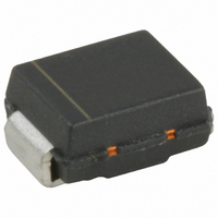
DIODE SCHOTTKY 40V 1A SMB
Manufacturer
Vishay
Specifications of MBRS140TR
Voltage - Forward (vf) (max) @ If
600mV @ 1A
Voltage - Dc Reverse (vr) (max)
40V
Current - Average Rectified (io)
1A
Current - Reverse Leakage @ Vr
100µA @ 40V
Diode Type
Schottky
Speed
Fast Recovery =< 500ns, > 200mA (Io)
Mounting Type
Surface Mount
Package / Case
DO-214AA, SMB
Product
Schottky Diodes
Peak Reverse Voltage
40 V
Forward Continuous Current
1 A
Max Surge Current
380 A
Configuration
Single
Forward Voltage Drop
0.77 V at 2 A
Maximum Reverse Leakage Current
100 uA
Operating Temperature Range
- 55 C to + 150 C
Mounting Style
SMD/SMT
Lead Free Status / RoHS Status
Contains lead / RoHS non-compliant
Reverse Recovery Time (trr)
-
Capacitance @ Vr, F
-
Lead Free Status / RoHS Status
Contains lead / RoHS non-compliant, Lead free / RoHS Compliant
Other names
VS-MBRS140TR
VS-MBRS140TR
VSMBRS140TR
VSMBRS140TR
VS-MBRS140TR
VSMBRS140TR
VSMBRS140TR
Available stocks
Company
Part Number
Manufacturer
Quantity
Price
Company:

Part Number:
MBRS140TR
Manufacturer:
IR
Quantity:
45 000
Company:
Part Number:
MBRS140TR
Manufacturer:
OSRAM
Quantity:
6 177
Company:
Part Number:
MBRS140TRPBF
Manufacturer:
IR
Quantity:
45 000


MBRS140TR
Bulletin PD-20591 rev. C 03/03
Thermal-Mechanical Specifications
2
Absolute Maximum Ratings
Electrical Specifications
Voltage Ratings
T
T
R
R
wt
(*) dPtot
(**) Mounted 1 inch square PCB
I
I
E
I
V
I
C
L
dv/dt Max. Voltage Rate of Change
V
V
(1) Pulse Width < 300µs, Duty Cycle < 2%
F(AV)
FSM
AR
RM
stg
S
J
thJL
FM
thJA
AS
T
R
RWM
dTj
Parameters
Parameters
Parameters
Max. Junction Temperature Range(*) - 55 to 150
Max. Storage Temperature Range
Max. Thermal Resistance
Junction to Lead
Max. Thermal Resistance
Junction to Ambient
Approximate Weight
Case Style
Device Marking
(Rated V
Max. Average Forward Current
Max. Peak One Cycle Non-Repetitive
Surge Current
Non- Repetitive Avalanche Energy
Repetitive Avalanche Current
Max. Forward Voltage Drop
Max. Reverse Leakage Current (1)
Max. Junction Capacitance
Typical Series Inductance
Part number
Max. DC Reverse Voltage (V)
Max. Working Peak Reverse Voltage (V)
<
Rth( j-a)
1
R
)
thermal runaway condition for a diode on its own heatsink
(1)
(**)
0.10 (0.003) g (oz.)
- 55 to 150
Value Units Conditions
Value
Typ.
0.52
0.70
0.48
0.63
380
3.0
1.0
1.0
40
36
80
-
-
-
-
-
SMB
IR14
10000
Units
°C/W DC operation (See Fig. 4)
°C/W DC operation
Max
0.77
0.53
0.71
0.6
0.1
4.0
2.0
mJ
80
°C
°C
A
A
A
Similar to DO-214AA
5µs Sine or 3µs Rect. pulse
T
Current decaying linearly to zero in 1 µsec
Frequency limited by T
50% duty cycle @ T
10ms Sine or 6ms Rect. pulse
Units
V/µs
J
mA
mA
nH
pF
V
V
V
V
= 25 °C, I
@ 1A
@ 2A
@ 1A
@ 2A
T
T
V
Measured lead to lead 5mm from package body
J
J
R
= 25°C
= 125°C
= 5V
AS
= 1A, L = 6mH
Conditions
Conditions
DC
(test signal range 100KHz to 1Mhz)25°C
MBRS140TR
L
= 119 °C, rectangular wave form
J
max. Va = 1.5 x Vr typical
V
T
T
40
J
R
J
= 125 °C
= 25 °C
= rated V
Following any rated
load condition and
with rated V
R
www.irf.com
RRM
applied
Related parts for MBRS140TR
Image
Part Number
Description
Manufacturer
Datasheet
Request
R

Part Number:
Description:
357-036-542-201 CARDEDGE 36POS DL .156 BLK LOPRO
Manufacturer:
Vishay
Datasheet:
Part Number:
Description:
357-036-542-201 CARDEDGE 36POS DL .156 BLK LOPRO
Manufacturer:
Vishay
Datasheet:
Part Number:
Description:
357-036-542-201 CARDEDGE 36POS DL .156 BLK LOPRO
Manufacturer:
Vishay
Datasheet:
Part Number:
Description:
357-036-542-201 CARDEDGE 36POS DL .156 BLK LOPRO
Manufacturer:
Vishay
Datasheet:
Part Number:
Description:
357-036-542-201 CARDEDGE 36POS DL .156 BLK LOPRO
Manufacturer:
Vishay
Datasheet:
Part Number:
Description:
357-036-542-201 CARDEDGE 36POS DL .156 BLK LOPRO
Manufacturer:
Vishay
Datasheet:
Part Number:
Description:
357-036-542-201 CARDEDGE 36POS DL .156 BLK LOPRO
Manufacturer:
Vishay
Datasheet:
Part Number:
Description:
357-036-542-201 CARDEDGE 36POS DL .156 BLK LOPRO
Manufacturer:
Vishay
Datasheet:
Part Number:
Description:
357-036-542-201 CARDEDGE 36POS DL .156 BLK LOPRO
Manufacturer:
Vishay
Datasheet:
Part Number:
Description:
357-036-542-201 CARDEDGE 36POS DL .156 BLK LOPRO
Manufacturer:
Vishay
Datasheet:
Part Number:
Description:
357-036-542-201 CARDEDGE 36POS DL .156 BLK LOPRO
Manufacturer:
Vishay
Datasheet:
Part Number:
Description:
357-036-542-201 CARDEDGE 36POS DL .156 BLK LOPRO
Manufacturer:
Vishay
Datasheet:
Part Number:
Description:
357-036-542-201 CARDEDGE 36POS DL .156 BLK LOPRO
Manufacturer:
Vishay
Datasheet:
Part Number:
Description:
357-036-542-201 CARDEDGE 36POS DL .156 BLK LOPRO
Manufacturer:
Vishay
Datasheet:
Part Number:
Description:
357-036-542-201 CARDEDGE 36POS DL .156 BLK LOPRO
Manufacturer:
Vishay
Datasheet: