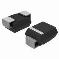
MBRS130T3G ON Semiconductor, MBRS130T3G Datasheet - Page 2

MBRS130T3G
Manufacturer Part Number
MBRS130T3G
Description
DIODE SCHOTTKY 30V 1A SMB
Manufacturer
ON Semiconductor
Specifications of MBRS130T3G
Voltage - Forward (vf) (max) @ If
600mV @ 1A
Voltage - Dc Reverse (vr) (max)
30V
Current - Average Rectified (io)
1A
Current - Reverse Leakage @ Vr
1mA @ 30V
Diode Type
Schottky
Speed
Fast Recovery =< 500ns, > 200mA (Io)
Mounting Type
Surface Mount
Package / Case
DO-214AA, SMB
Product
Schottky Diodes
Peak Reverse Voltage
30 V
Forward Continuous Current
1 A
Max Surge Current
40 A
Configuration
Single
Forward Voltage Drop
0.6 V
Maximum Reverse Leakage Current
1000 uA
Operating Temperature Range
- 65 C to + 125 C
Mounting Style
SMD/SMT
Current, Forward
1 A
Current, Reverse
10 mA
Current, Surge
40 A
Package Type
SMB
Primary Type
Schottky Barrier
Temperature, Junction, Maximum
+125 °C
Temperature, Operating
-65 to +125 °C
Voltage, Forward
0.6 V
Voltage, Reverse
30 V
Lead Free Status / RoHS Status
Lead free / RoHS Compliant
Reverse Recovery Time (trr)
-
Capacitance @ Vr, F
-
Lead Free Status / Rohs Status
Lead free / RoHS Compliant
Other names
MBRS130T3GOSTR
Available stocks
Company
Part Number
Manufacturer
Quantity
Price
Company:
Part Number:
MBRS130T3G
Manufacturer:
ON
Quantity:
12 500
Company:
Part Number:
MBRS130T3G
Manufacturer:
INTERNAL
Quantity:
514
Part Number:
MBRS130T3G
Manufacturer:
ON/安森美
Quantity:
20 000
1. Pulse Test: Pulse Width = 300 ms, Duty Cycle ≤ 2.0%.
ELECTRICAL CHARACTERISTICS
Maximum Instantaneous Forward Voltage (Note 1)
Maximum Instantaneous Reverse Current (Note 1)
0.07
0.05
0.03
0.02
10
0.7
0.5
0.3
0.2
0.1
9
8
7
6
5
4
3
2
1
0
(i
(Rated dc Voltage, T
(Rated dc Voltage, T
30
1
0.1
F
= 1.0 A, T
T
C
40
= 100°C
0.2
v
F
, INSTANTANEOUS FORWARD VOLTAGE (VOLTS)
Figure 1. Typical Forward Voltage
50
J
0.3
T
Figure 4. Current Derating (Case)
= 25°C)
C
= 25°C
60
0.4
SQUARE WAVE
T
C
J
J
, CASE TEMPERATURE (°C)
= 25°C)
= 100°C)
70
0.5
80
0.6
200
180
160
140
120
100
Rating
80
60
40
20
RATED VOLTAGE APPLIED
0
0
90
0.7
DC
R
qJC
T
100
4
0.8
J
= 125°C
= 12°C/W
110
8
0.9
Figure 3. Typical Capacitance
V
http://onsemi.com
12
R
120
, REVERSE VOLTAGE (VOLTS)
1
MBRS130T3
16
130
1.1
2
NOTE: TYPICAL CAPACITANCE
0.05
0.03
0.02
0.01
20
100
0.5
0.3
0.2
0.1
50
30
20
10
5
3
2
1
5
4
3
2
1
0
0
0
AT 0 V = 160 pF
24
CAPACITANCE
T
J
I
I
AV
PK
4
= 125°C
LOAD
28
=
I
F(AV)
20
Figure 2. Typical Reverse Current
8
1
Figure 5. Power Dissipation
Symbol
32
, AVERAGE FORWARD CURRENT (AMPS)
V
i
R
12
V
F
R
10
, REVERSE VOLTAGE (VOLTS)
36
16
2
40
T
20
J
5
75°C
25°C
= 125°C
100°C
24
3
Value
π
SQUARE
0.6
1.0
10
WAVE
28
32
4
DC
36
Unit
mA
V
40
5


