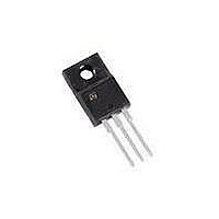
STGF10NC60SD STMicroelectronics, STGF10NC60SD Datasheet - Page 7

STGF10NC60SD
Manufacturer Part Number
STGF10NC60SD
Description
IGBT 600V 10A 25W TP220FP
Manufacturer
STMicroelectronics
Series
PowerMESH™r
Datasheet
1.STGD10NC60SDT4.pdf
(16 pages)
Specifications of STGF10NC60SD
Voltage - Collector Emitter Breakdown (max)
600V
Vce(on) (max) @ Vge, Ic
1.65V @ 15V, 5A
Current - Collector (ic) (max)
10A
Power - Max
25W
Input Type
Standard
Mounting Type
Through Hole
Package / Case
TO-220-3 Full Pack (Straight Leads)
Collector- Emitter Voltage Vceo Max
600 V
Collector-emitter Saturation Voltage
1.45 V
Maximum Gate Emitter Voltage
20 V
Continuous Collector Current At 25 C
10 A
Gate-emitter Leakage Current
100 nA
Power Dissipation
25 W
Mounting Style
Through Hole
Lead Free Status / RoHS Status
Lead free / RoHS Compliant
Igbt Type
-
Lead Free Status / Rohs Status
Lead free / RoHS Compliant
Other names
497-10003-5
Available stocks
Company
Part Number
Manufacturer
Quantity
Price
STGD10NC60SD, STGF10NC60SD
Figure 8.
Figure 10. Switching losses vs temperature
Figure 12. Switching losses vs collector
E (µJ)
E (µJ)
C (pF)
500
400
300
200
100
600
500
400
300
200
100
600
400
200
0
0
0
25
1
0
C
Capacitance variations
current
res
V
E
E
R
CC
OFF
ON
10
G
= 480 V, V
50
=10 Ω, T
2
C
V
oes
CC
I
C
= 480 V, V
= 5 A, R
20
J
f = 1 MHz
GE
= 125 °C
V
75
GE
= 15 V
3
= 0
G
GE
=10 Ω
30
= 15 V
100
4
C
40
ies
E
E
OFF
AM07270v1
ON
AM07272v1
AM07269v1
T
J
I
V
C
(°C)
Doc ID 15847 Rev 2
CE
(A)
Figure 9.
Figure 11. Switching losses vs gate resistance
Figure 13. Diode forward on voltage
E (µJ)
600
500
400
300
200
100
V
GE
0
(V)
20
16
12
0
8
4
0
0
Gate charge vs gate-emitter voltage
E
E
40
OFF
ON
4
V
80
CC
I
C
= 480 V, V
= 5 A, T
8
V
Electrical characteristics
CC
I
C
120
= 480 V
= 5 A
12
J
= 125 °C
GE
160
= 15 V
16
200
Q
AM07268v1
AM07271v1
G
(nC)
R
G
(Ω)
7/16


