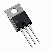
IRG4IBC30KDPBF International Rectifier, IRG4IBC30KDPBF Datasheet

IRG4IBC30KDPBF
Specifications of IRG4IBC30KDPBF
Available stocks
Related parts for IRG4IBC30KDPBF
IRG4IBC30KDPBF Summary of contents
Page 1
Features θ θ θ www.irf.com n-channel TO-220 FULLP AK … ‚… CES = CE(on) typ ...
Page 2
J ∆ ∆ ƒ „ J Ω Ω Ω www.irf.com ...
Page 3
Square wave: 60% of rated 6 voltage I 4 Ideal diodes 2 0 0.1 100 150 20µs PULSE WIDTH 0 ...
Page 4
T , Case Temperature ( 0.50 1 0.20 0.10 0.05 0.1 0.02 0.01 SINGLE PULSE (THERMAL RESPONSE) 0.01 0.00001 0.0001 4 4 15V GE ...
Page 5
1MHz ies res 1200 oes ies 900 600 C oes 300 C res ...
Page 6
R = Ohm 150 C ° 480V 15V 4.0 GE 3.0 2.0 1.0 0 Collector-to-emitter Current (A) C 100 10 1 0.4 6 ...
Page 7
V = 200V 125° 25°C J 120 I = 24A 12A 100 di /dt - (A/µs) f 600 V = 200V 125°C J ...
Page 8
Same type device as D.U.T. 430µF 80% of Vce D.U. off(diode d(on) GATE VOLTAGE D.U.T. 10% +Vg +Vg Vce 10% Ic Vcc 90 Vce tr td(on d(on +Vge 10% ...
Page 9
Figure 18e. Macro Waveforms for L 1000V 50V 6000µF 100V Figure 19. Clamped Inductive Load Test Circuit www.irf.com Vg GATE SIGNAL DEVICE UNDER TEST CURRENT D.U.T. VOLTAGE IN D.U.T. CURRENT Figure 18a's D.U. ...
Page 10
TO-220AB Full-Pak Package Outline Dimensions are shown in millimeters (inches) TO-220AB Full-Pak Part Marking Information TO-220AB Full-Pak package is not recommended for Surface Mount Application. GE ‚ CC CES GE ƒ ≤ „ … IR WORLD HEADQUARTERS: 233 Kansas ...


