PTCTZ3MR250HTE Vishay, PTCTZ3MR250HTE Datasheet - Page 2
PTCTZ3MR250HTE
Manufacturer Part Number
PTCTZ3MR250HTE
Description
PTC TE HOR 6D50 25R0 265 MAT T HM
Manufacturer
Vishay
Series
661r
Type
PTCr
Datasheets
1.PTCTZ3NR339CTE.pdf
(2 pages)
2.PTCTZ3MR250HTE.pdf
(3 pages)
3.PTCTZ3MR250HTE.pdf
(3 pages)
Specifications of PTCTZ3MR250HTE
Voltage - Max
265V
Time To Trip
1.3s
Current - Hold (ih) (max)
120mA
Current - Trip (it)
220mA
Current - Max
2A
Package / Case
Non-Standard SMD
Description Of Terminals
Leadless
Mounting Style
Surface Mount
Pin Count
2
Resistance @ 25c
25Ohm
Percentage Of Resistance Tolerance @ 25c
±20
Product Length (mm)
7.2mm
Product Height (mm)
2mm
Product Depth (mm)
8mm
Resistance
25 Ohms
Tolerance
20 %
Termination Style
SMD/SMT
Lead Free Status / RoHS Status
Contains lead / RoHS non-compliant
R Min/max
-
Lead Free Status / Rohs Status
Lead free / RoHS Compliant
Other names
2322 661 97005
232266197005
BC1563TR
PTCTZ3MR250HTX
232266197005
BC1563TR
PTCTZ3MR250HTX


www.vishay.com
2
2322 661 97...
Vishay BCcomponents
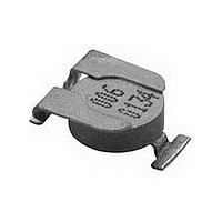
PTC OUTLINES
PTC SMD ceramic size: 6.5 mm.
DIMENSIONS in millimeters
SOLDERING CONDITIONS
This SMD thermistor is only suitable for reflow soldering, in accordance with “CECC 00802” . Soldering processes which can be
used are reflow (infrared and convection heating) and vapour phase. The maximum temperature of 260 ° C during 10 s should
not be exceeded and no liquid flux should be allowed to reach the ceramic body.
Typical examples of a soldering processes that will provide reliable joints without damage, are shown below.
HANDLING PRECAUTIONS
The special leadframe construction and the applied processes do not allow high handling forces on the component.
Because of the nature of PTC ceramic material the component should not be touched with bare hands, as the residue of
perspiration can influence component behaviour at high temperatures.
Handling forces vertically applied to the centre of the component should be limited to 5 N in the non-soldered condition and to
10 N in the soldered. These forces should not be exceeded during the handling, transportation and packaging of the soldered
product.
For those applications where higher handling forces can be present, a re-inforced version is available on request.
Reflow soldering.
Typical values (solid line).
Process limits (dotted lines).
±0.15
3.45
2.8
( C)
T
300
250
200
150
100
50
0
0
1
7.2
3.6 ±0.1
4 ±0.2
4 ±0.1
−0.2
0
50
2
2 K/s
max.
10°
100
3
130 C
2
1.2
260 C
245 C
215 C
180 C
150
3
10 s
10 s
40 s
2
7.6 ±0.25
10 ±0.25
8.0
200
Horizontal Surface Mount PTC Thermistors
For technical questions contact: nlr.europe@vishay.com
0.6
t (s)
1
+0.6
0
250
For Overload Protection
0.2
Typical values (solid line).
Process limits (dotted lines).
Vapour phase soldering.
DIMENSIONS OF SOLDER LANDS in millimeters
REF.
MATERIAL INFORMATION
1
2
3
( C)
T
300
250
200
150
100
50
0
DESCRIPTION
0
external preheating
metallization
5
leadframe
ceramic
215 C
180 C
130 C
100 C
2
50
internal preheating,
e.g. by infrared,
max. 2 K/s
100
11
Ni plated phosphor bronze material
covered by PbSn8 solder layer
20 to 40 s
MATERIAL AND REMARKS
150
(vacuum deposition)
Document Number: 29068
BaTiO3 doped
NiCr Ag layer
200
Revision: 07-Sep-04
forced
cooling
t (s)
250
Related parts for PTCTZ3MR250HTE
Image
Part Number
Description
Manufacturer
Datasheet
Request
R

Part Number:
Description:
357-036-542-201 CARDEDGE 36POS DL .156 BLK LOPRO
Manufacturer:
Vishay
Datasheet:
Part Number:
Description:
357-036-542-201 CARDEDGE 36POS DL .156 BLK LOPRO
Manufacturer:
Vishay
Datasheet:
Part Number:
Description:
357-036-542-201 CARDEDGE 36POS DL .156 BLK LOPRO
Manufacturer:
Vishay
Datasheet:
Part Number:
Description:
357-036-542-201 CARDEDGE 36POS DL .156 BLK LOPRO
Manufacturer:
Vishay
Datasheet:
Part Number:
Description:
357-036-542-201 CARDEDGE 36POS DL .156 BLK LOPRO
Manufacturer:
Vishay
Datasheet:
Part Number:
Description:
357-036-542-201 CARDEDGE 36POS DL .156 BLK LOPRO
Manufacturer:
Vishay
Datasheet:
Part Number:
Description:
357-036-542-201 CARDEDGE 36POS DL .156 BLK LOPRO
Manufacturer:
Vishay
Datasheet:
Part Number:
Description:
357-036-542-201 CARDEDGE 36POS DL .156 BLK LOPRO
Manufacturer:
Vishay
Datasheet:
Part Number:
Description:
357-036-542-201 CARDEDGE 36POS DL .156 BLK LOPRO
Manufacturer:
Vishay
Datasheet:
Part Number:
Description:
357-036-542-201 CARDEDGE 36POS DL .156 BLK LOPRO
Manufacturer:
Vishay
Datasheet:
Part Number:
Description:
357-036-542-201 CARDEDGE 36POS DL .156 BLK LOPRO
Manufacturer:
Vishay
Datasheet:
Part Number:
Description:
357-036-542-201 CARDEDGE 36POS DL .156 BLK LOPRO
Manufacturer:
Vishay
Datasheet:
Part Number:
Description:
357-036-542-201 CARDEDGE 36POS DL .156 BLK LOPRO
Manufacturer:
Vishay
Datasheet:
Part Number:
Description:
357-036-542-201 CARDEDGE 36POS DL .156 BLK LOPRO
Manufacturer:
Vishay
Datasheet:
Part Number:
Description:
357-036-542-201 CARDEDGE 36POS DL .156 BLK LOPRO
Manufacturer:
Vishay
Datasheet: